Week 16
System Integration
Fab Academy 2024
Riichiro Yamamoto
Dear My Friend
This week I took some time off from developing the final project and spent time to package the project, such as figuring out how the machine should work without having scattered electronics and also allocating all the modules and components in a nice cleaner package.
Hope you enjoy
Riichiro Yamamoto
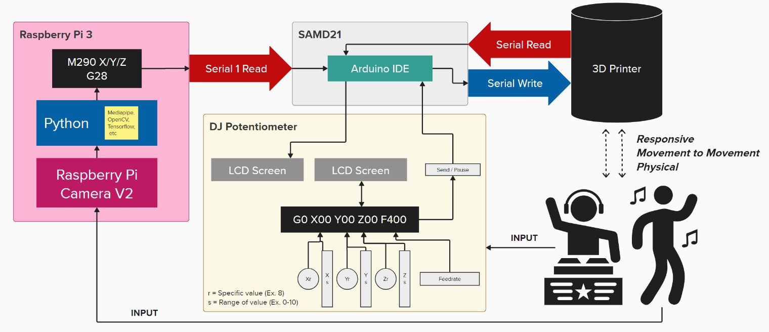
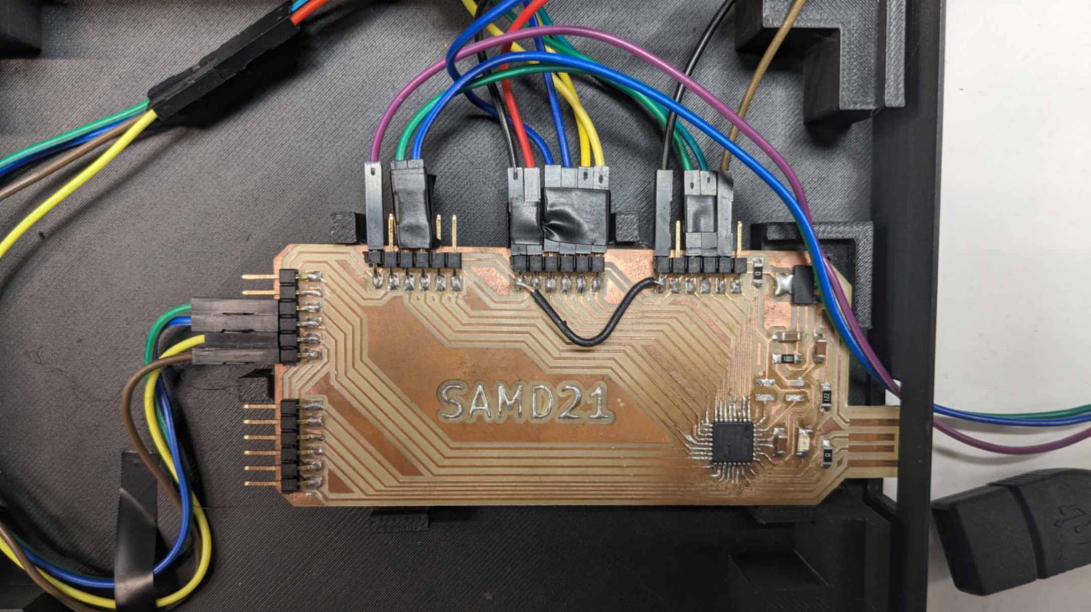
Software System Diagram
I made a software system integration diagram for me to visualize how all of the parts should be connected and how the communication needs to be done. Through doing this it became clear that SAMD21 PCB will be doing the idle man role to receive value from potentiometer and Raspberry Pi then send the value to Arduino Mega+RAMPS to move the printer.
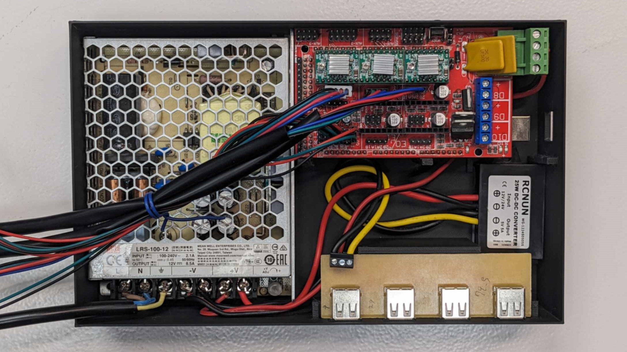
USB Power Ports
Before I started designing packaging for the system integration, I needed to figure out a way to power multiple devices without plugging each into sockets or PCs
After I had spoken to my tutor, I decided to make multiple USB power ports that would spread voltage from the power supply used for the 3d printer.
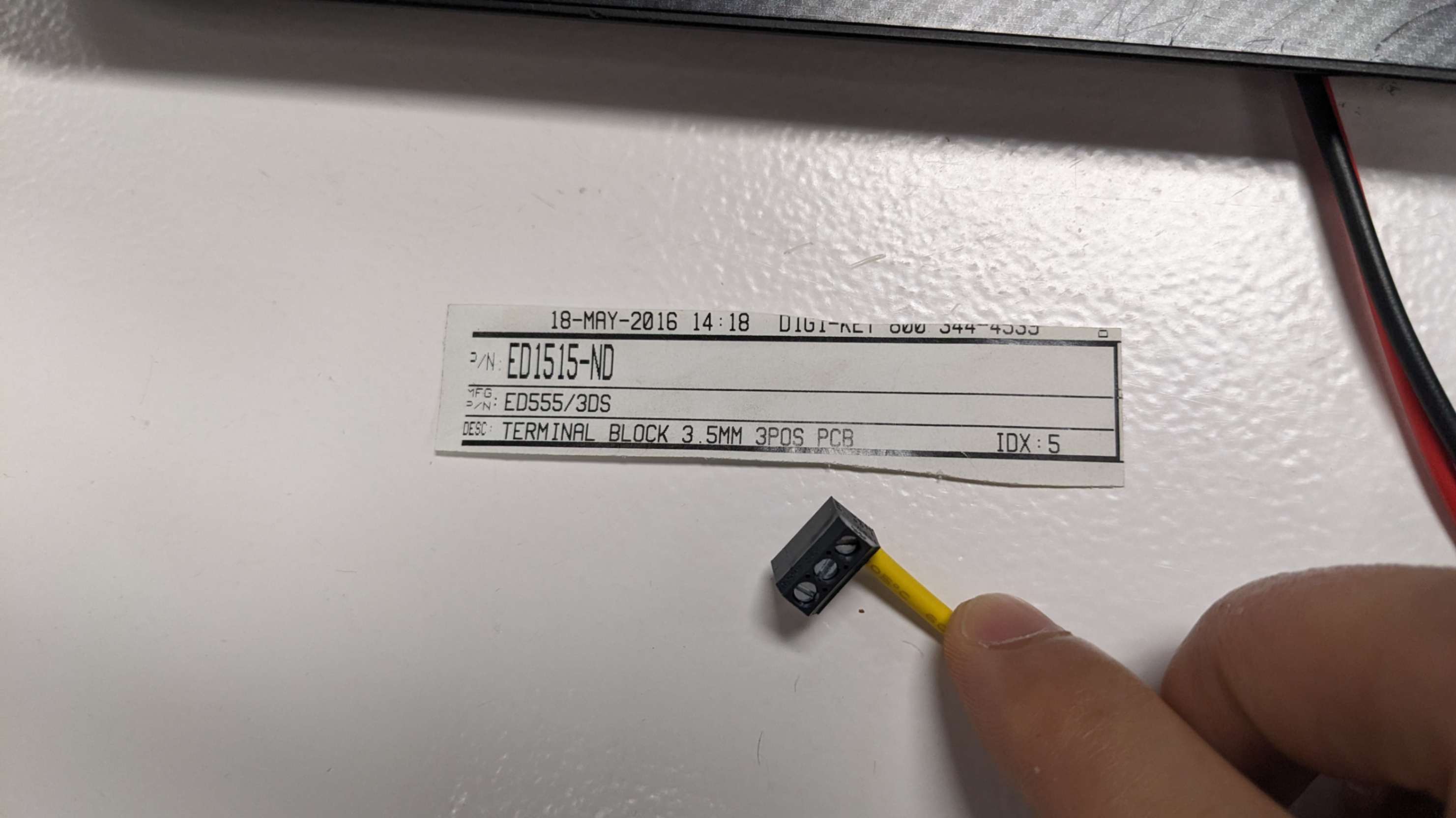
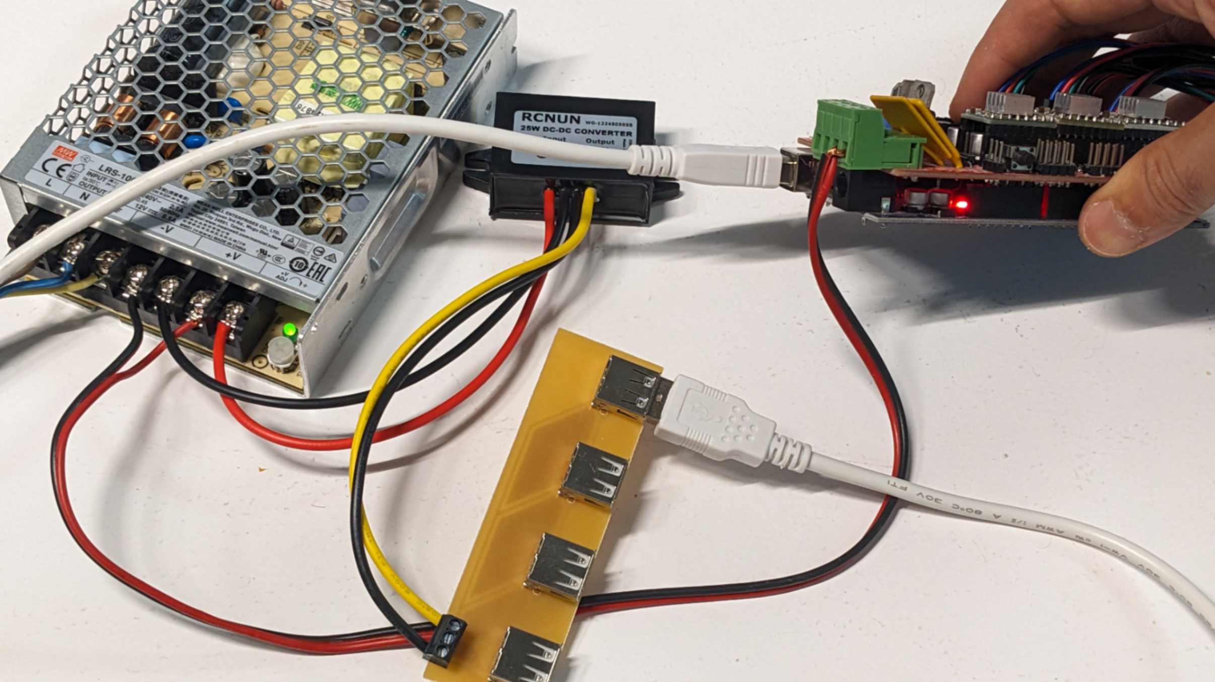
Since the power supply for the 3D printer works with 12V, I needed to use a DC-DC Converter (RCNUN WG-1224S0505S) to convert it to 5V. For connection, I used a 3pos terminal block (ED1515-ND)
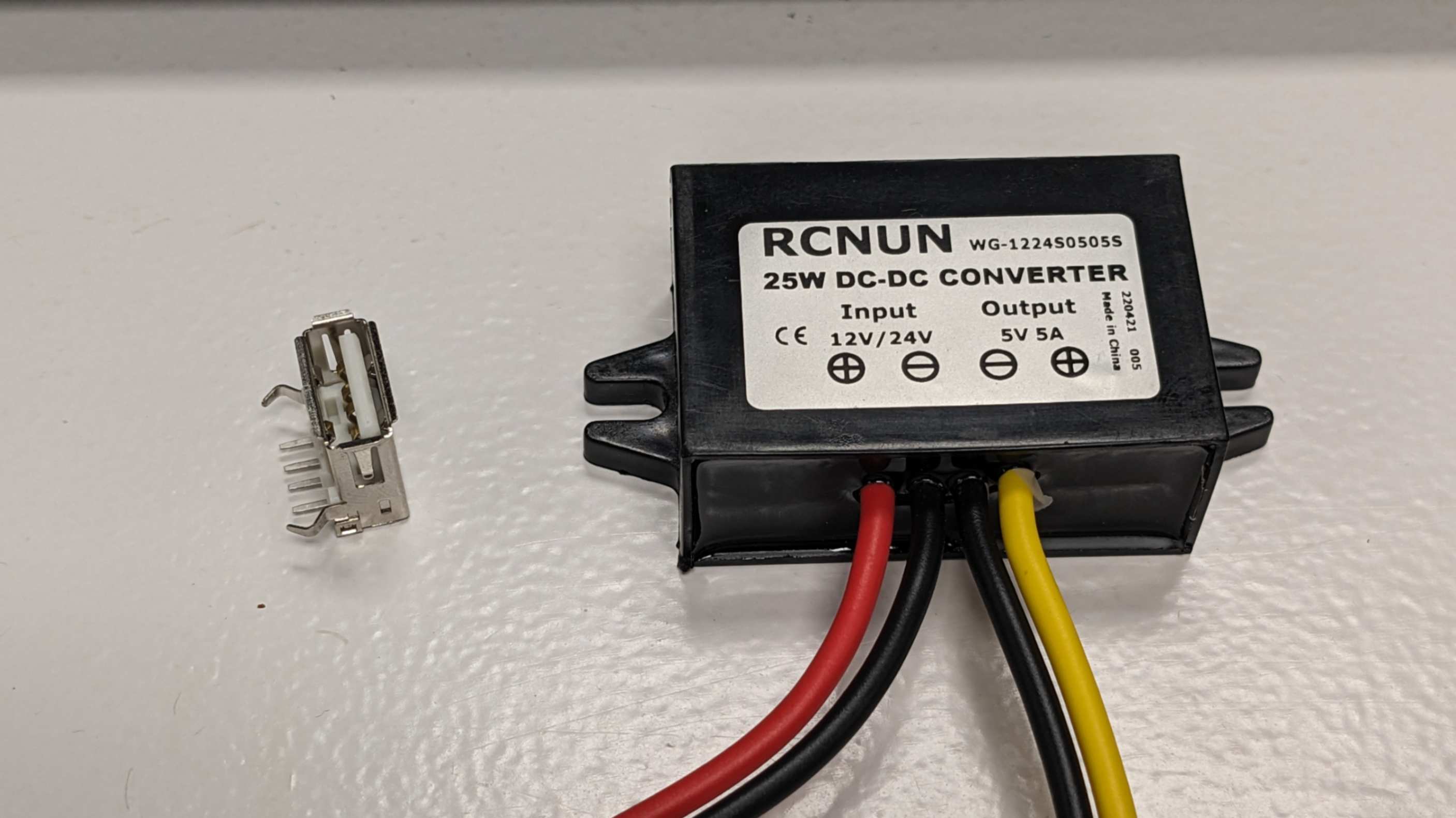
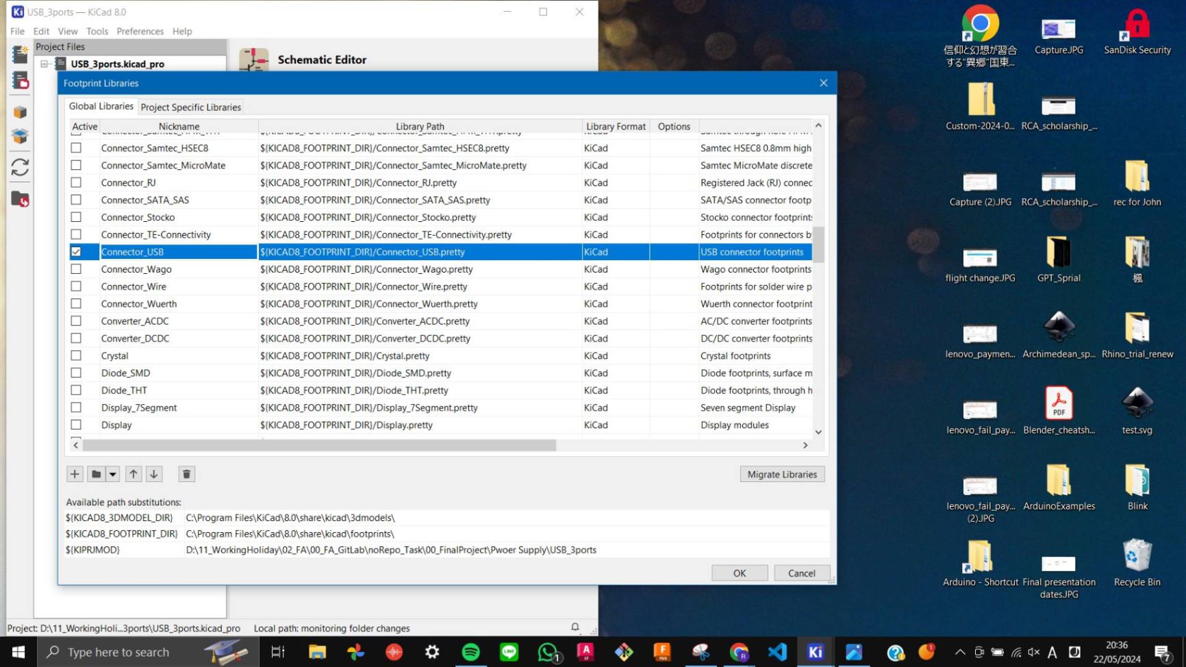
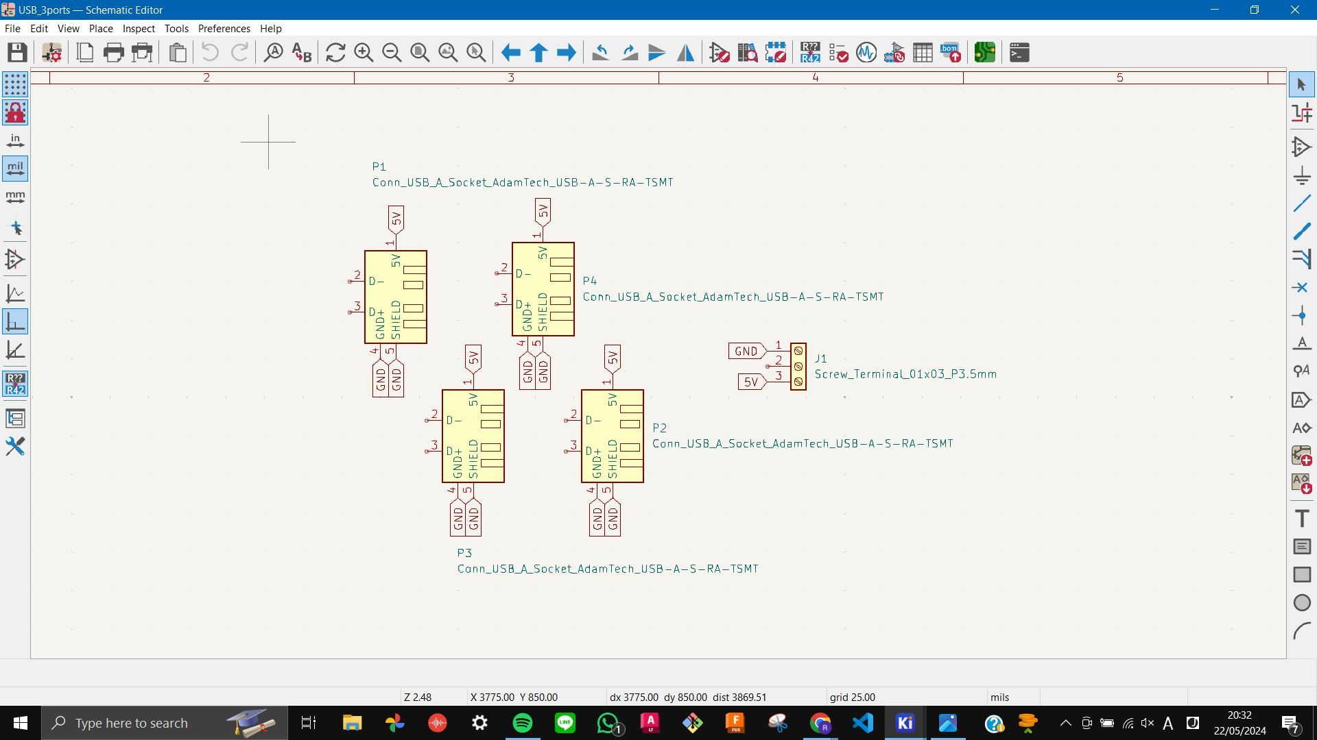
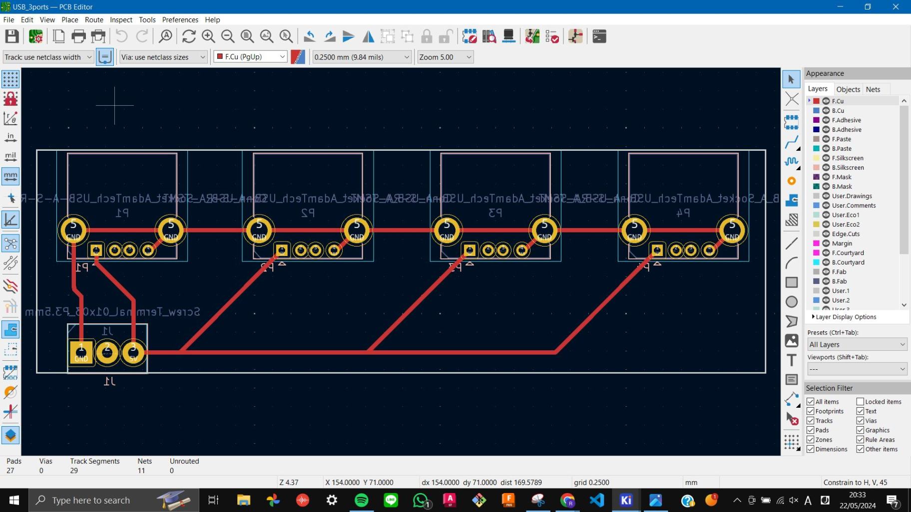
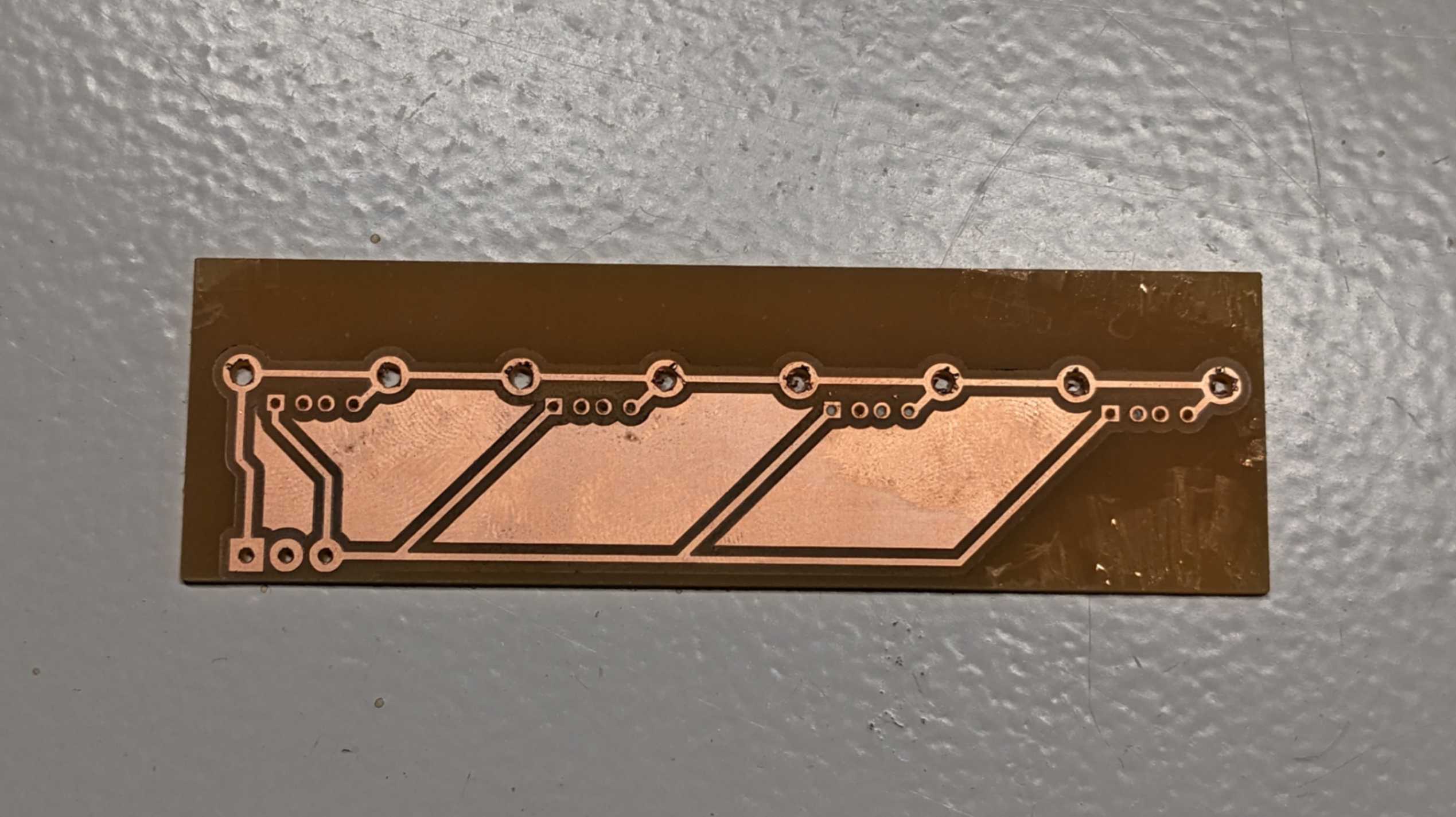
Then I took 4 USB A female sockets and made a PCB board. Designing this PCB was fairly simple but one thing I needed to be careful of was to flip the footprints because the components that I grabbed were meant to be soldered from the backside.
USB_4ports-F_Cu_Flipped.svg
USB_4ports.kicad_pcb
USB_4ports.kicad_prl
USB_4ports.kicad_pro
USB_4ports.kicad_sch

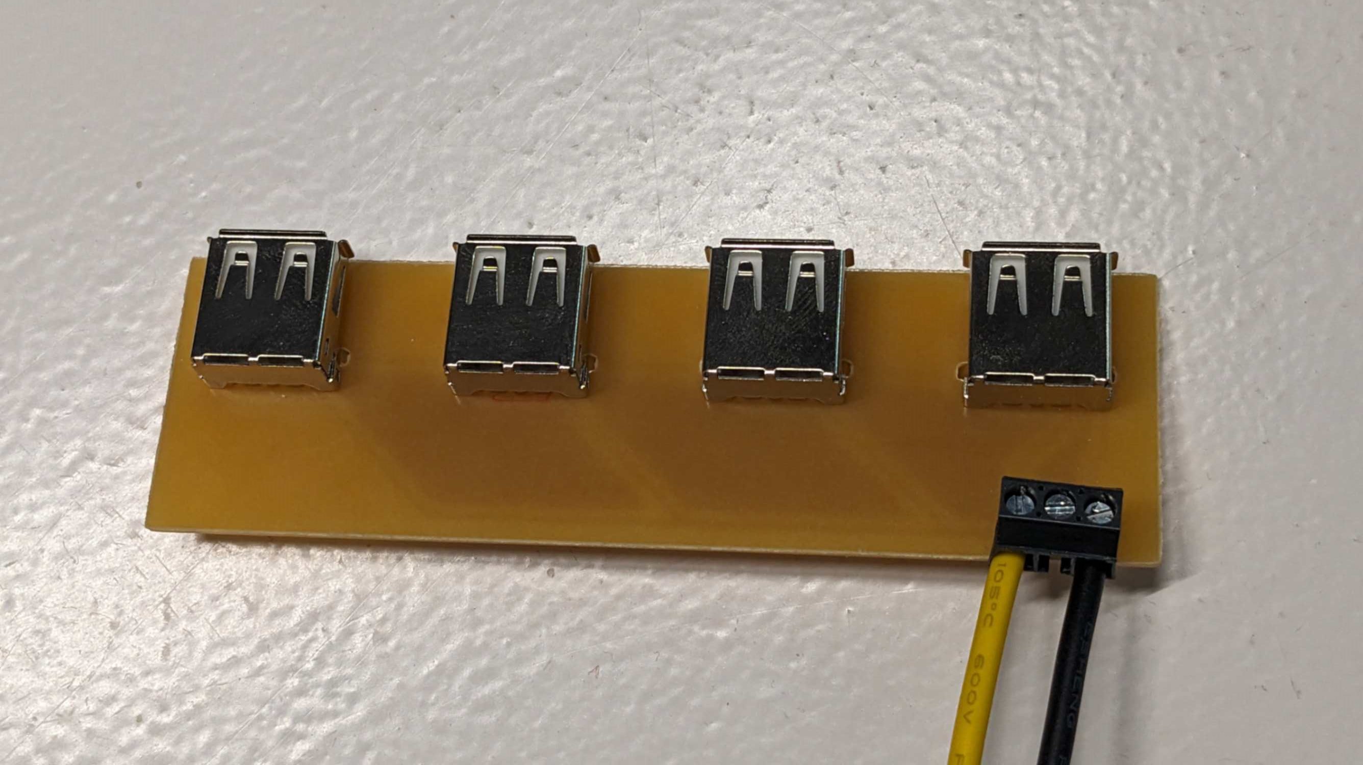
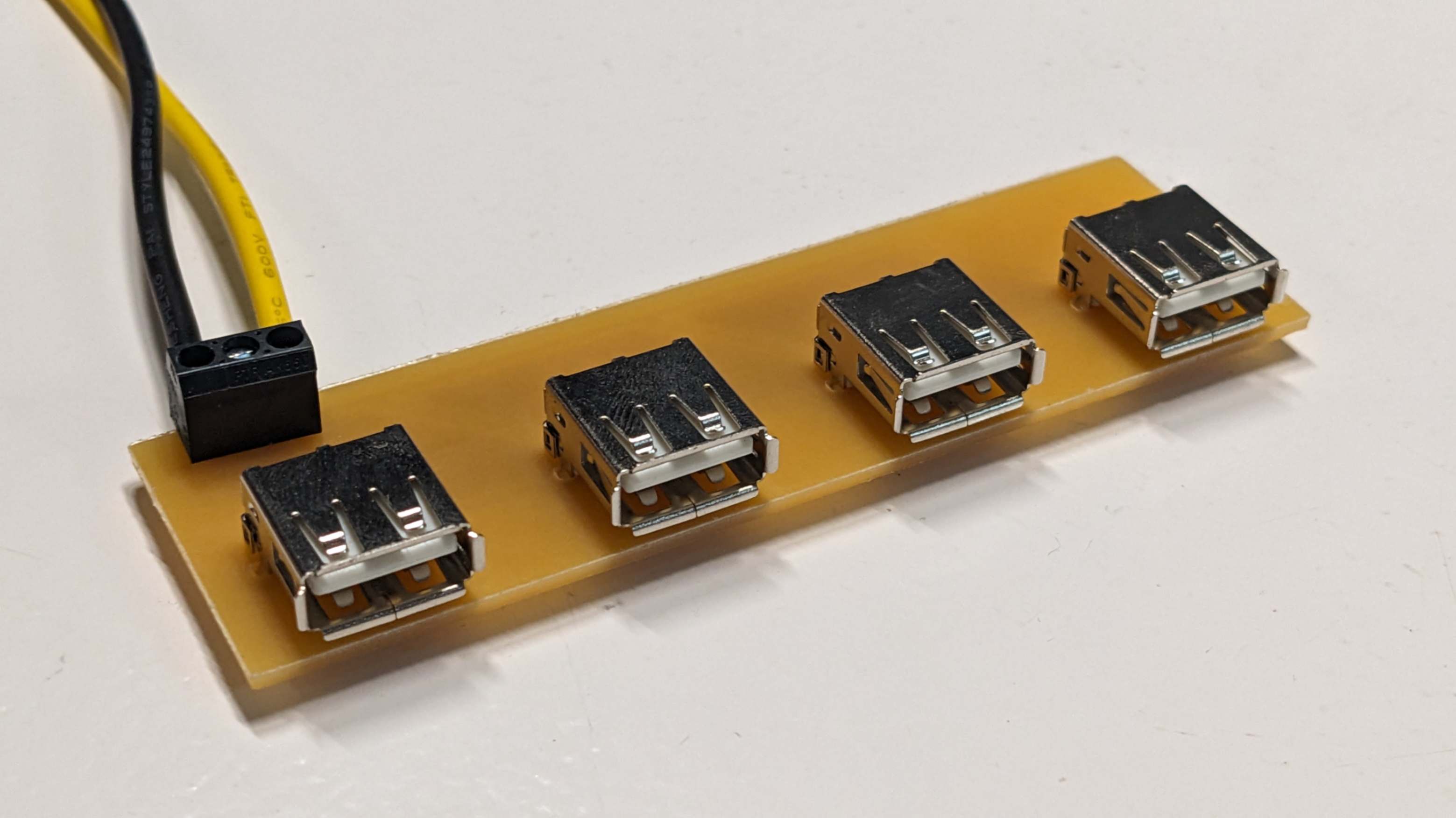
After successfully making the PCB, I simply connected the input wire of the converter to -V and +V of the power supply, and the output wire to the terminal block on the PCB. As a result, all the USB port was powered.
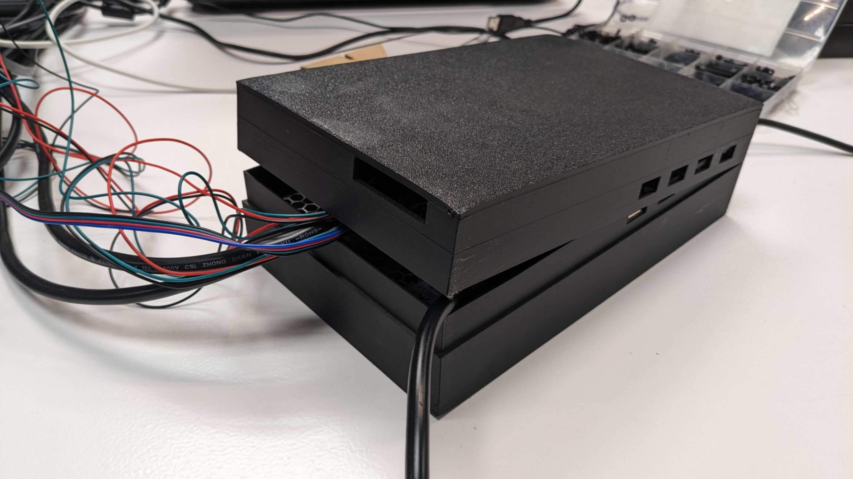
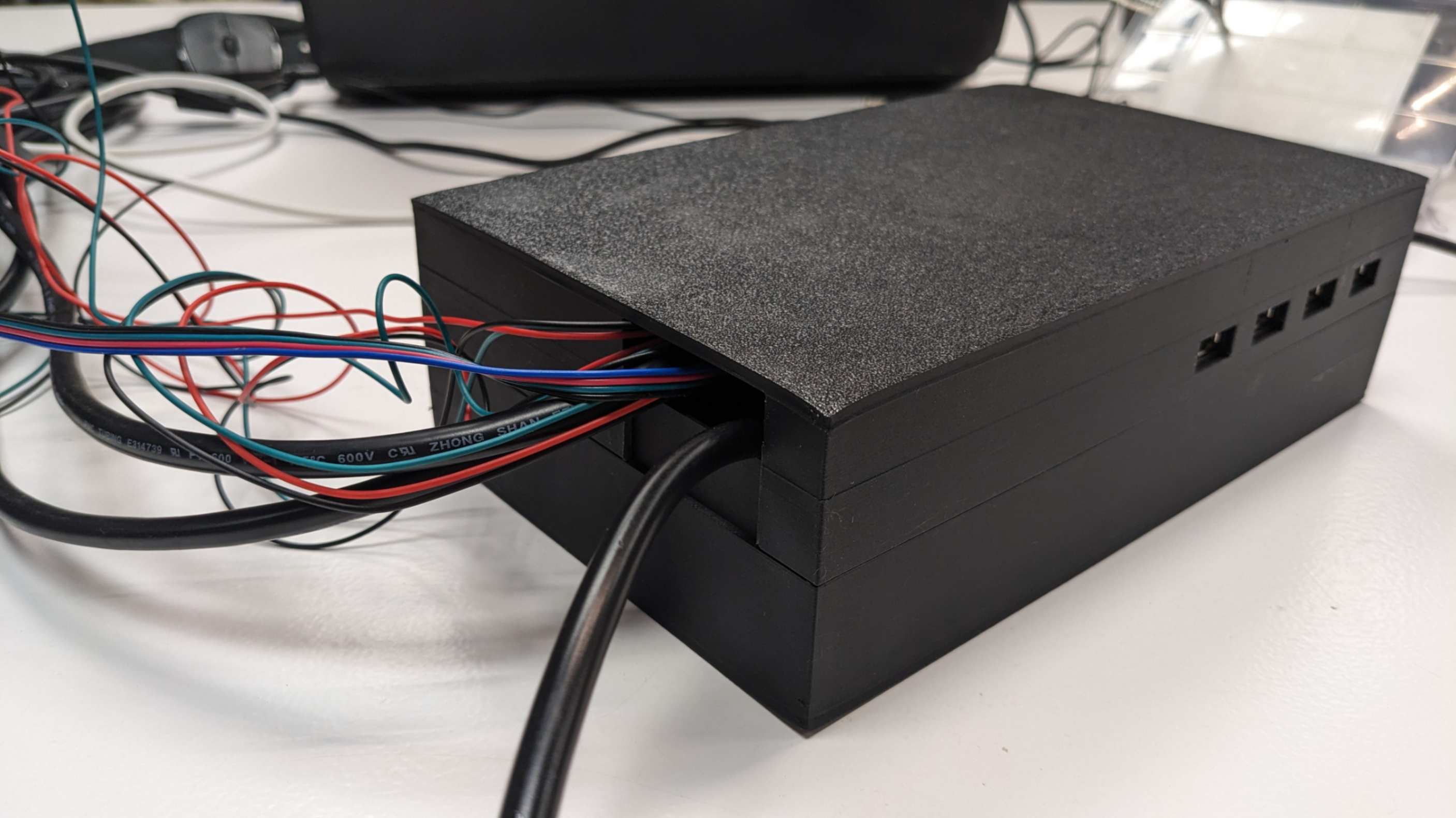
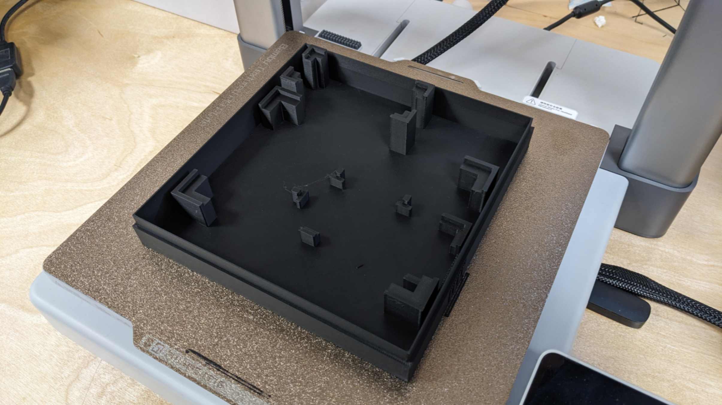
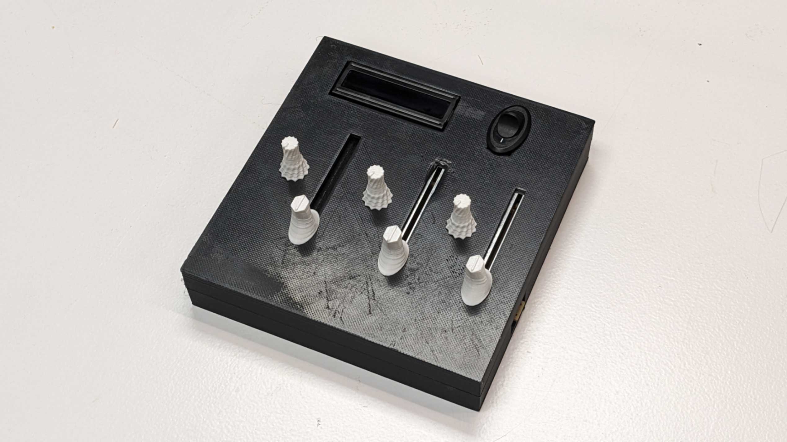
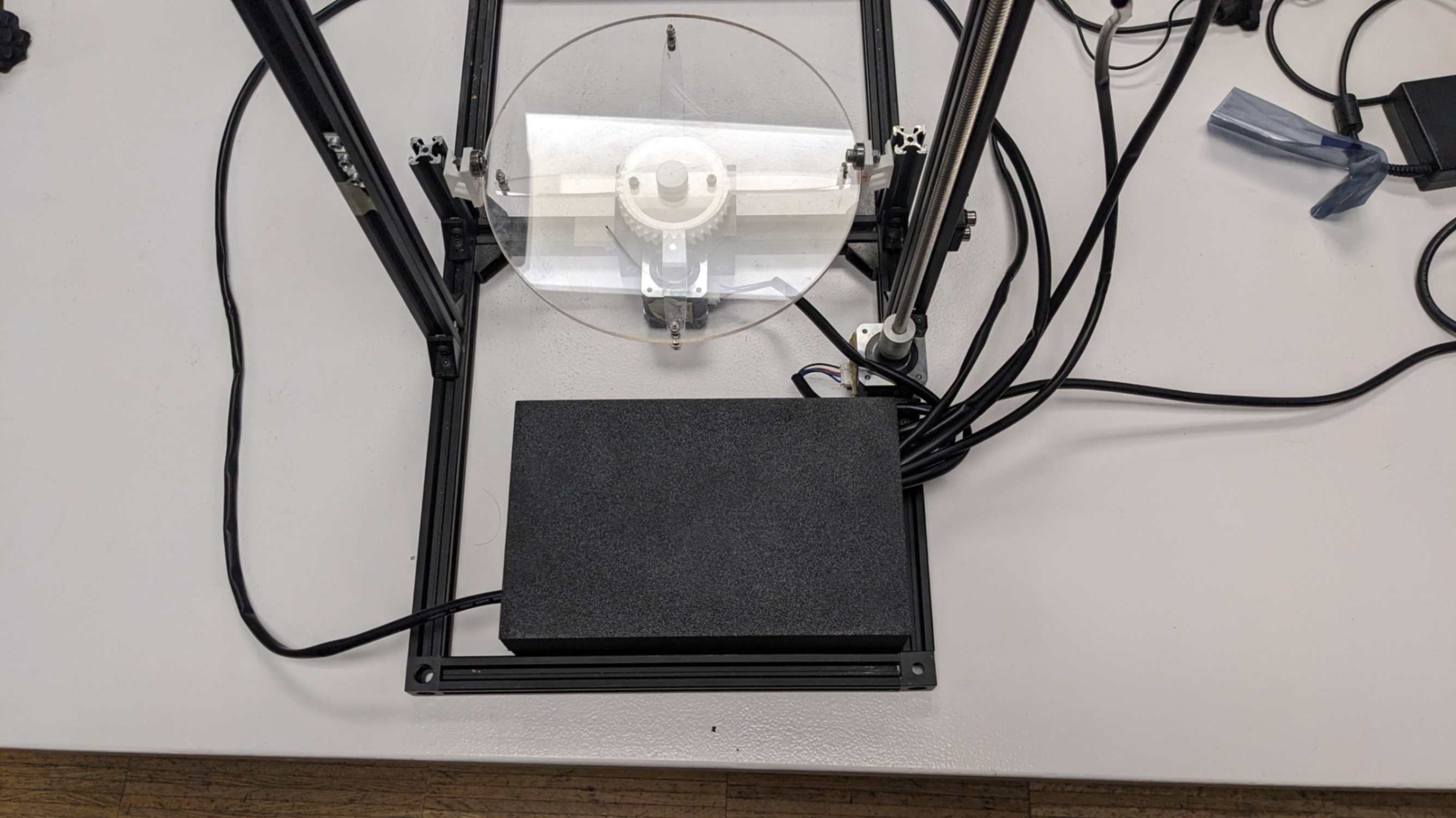
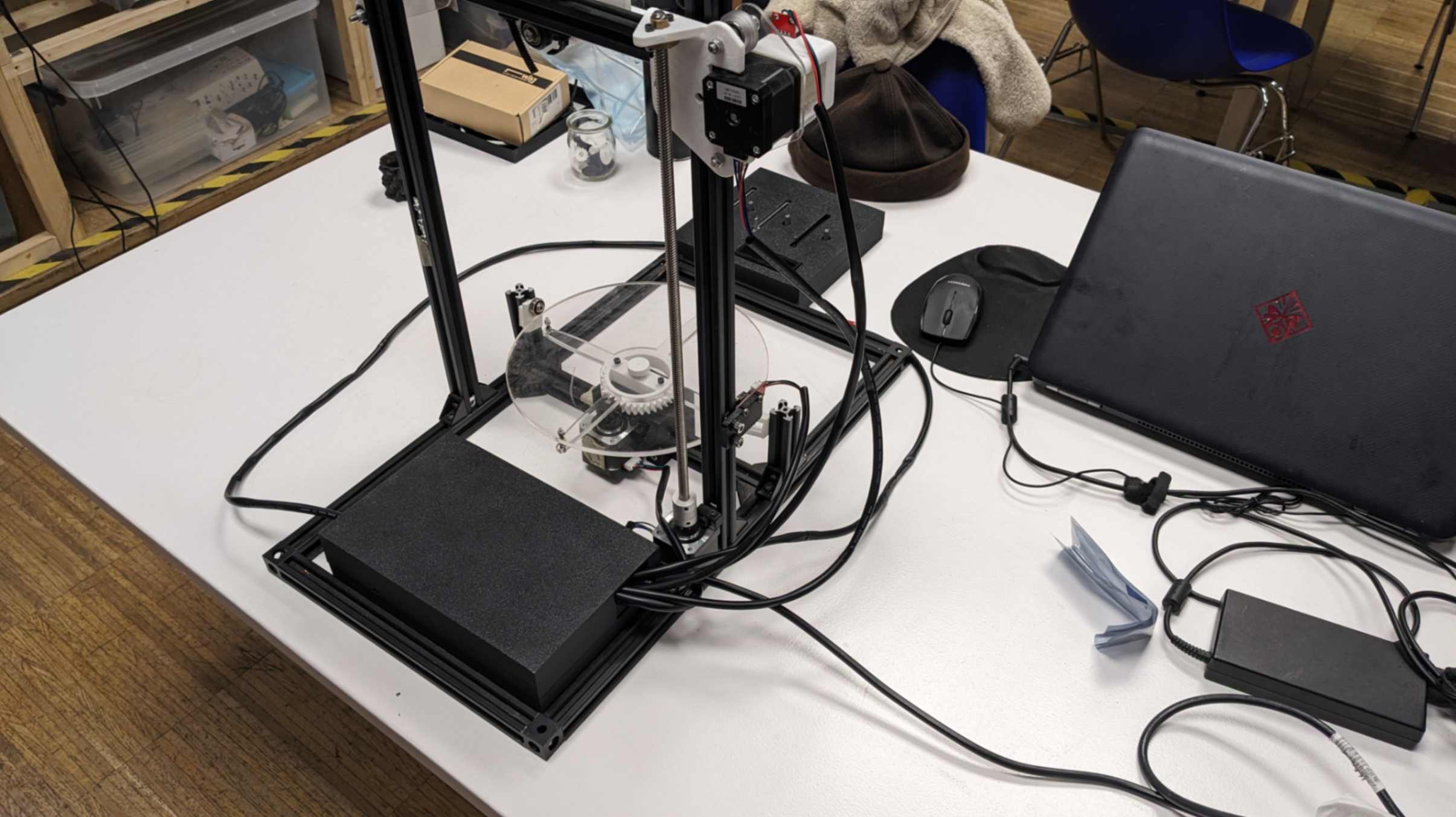
Bento Box
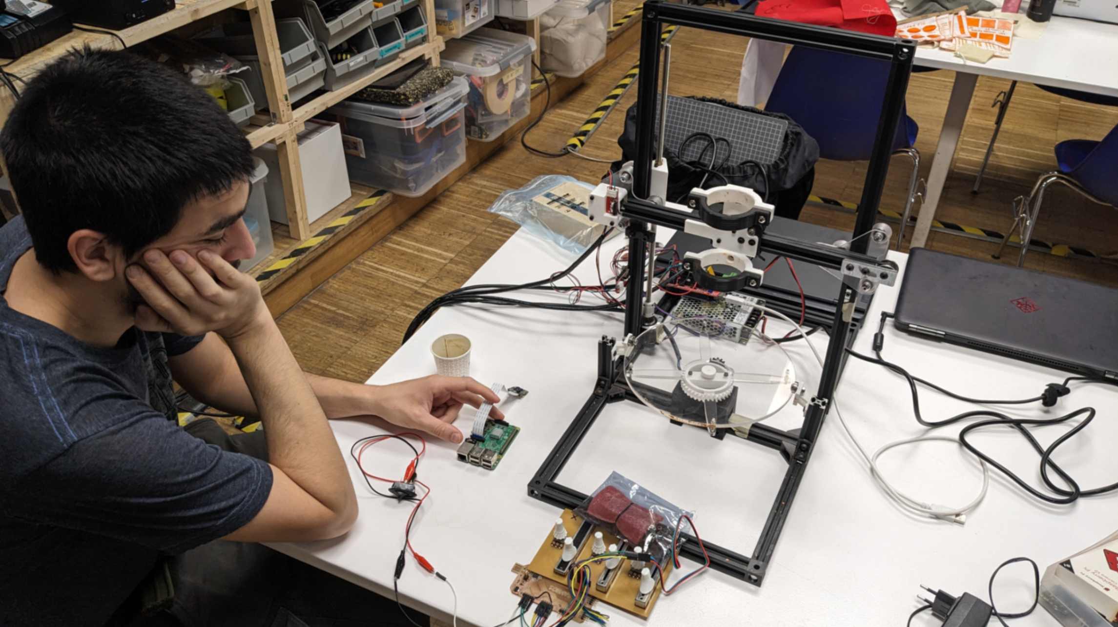
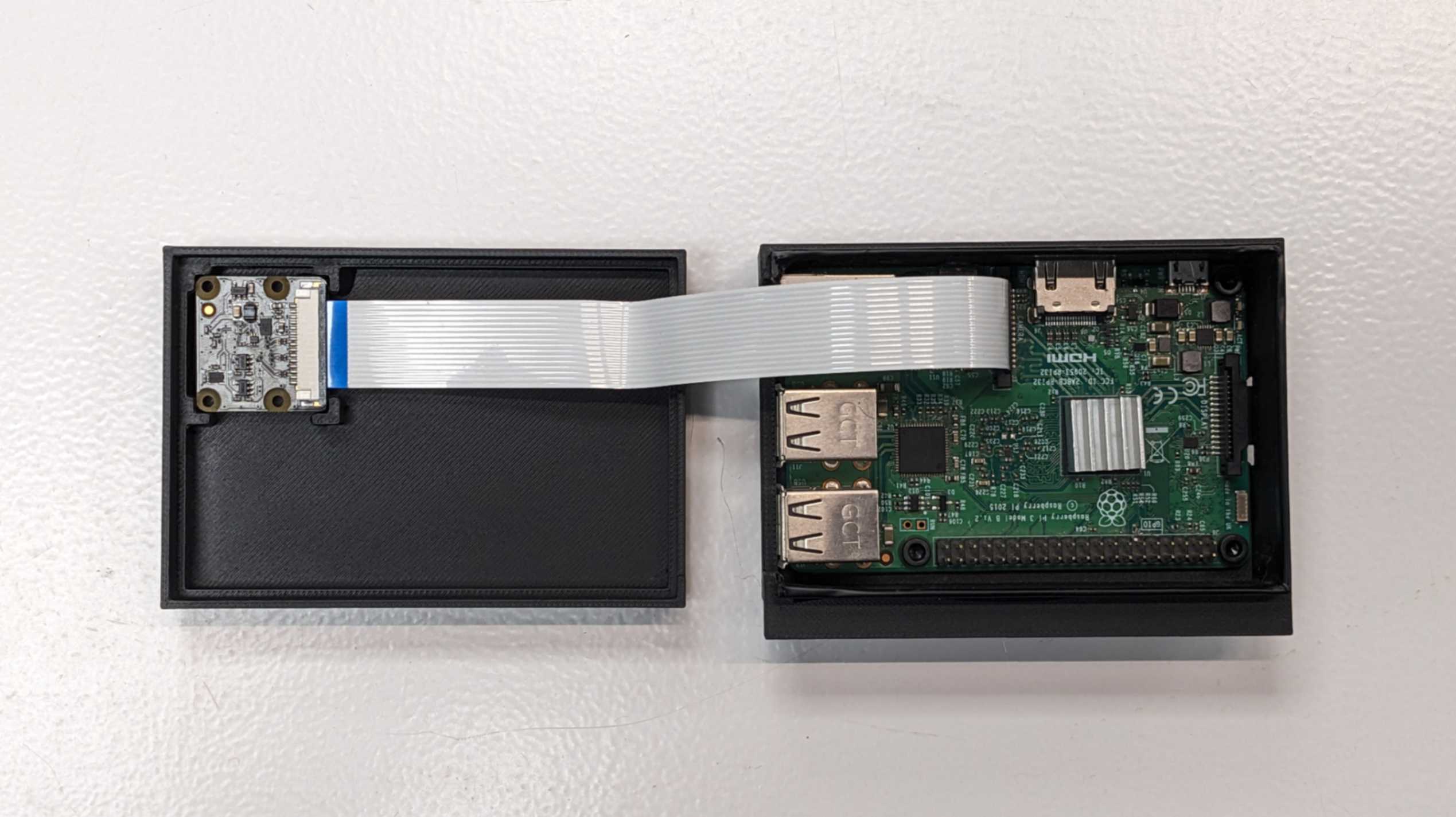
First I organised all the devices and electronics that are part of my final project. There were 3 groups. One is the components of the 3D printer. Second, is the components of the DJ set. Third is the components that are used for motion capture. So I decided to make a separate packaging for each. Since my final project is about 3D printing, I wanted to make packaging with 3D-printed pieces.
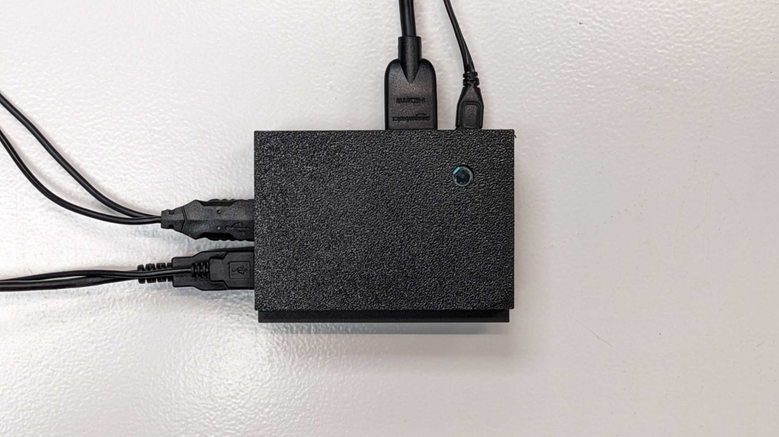
Next, I measured and roughly placed those components to figure out how they should fit in the packaging. (for Raspberry Pi, I used a 3D model from this page.)
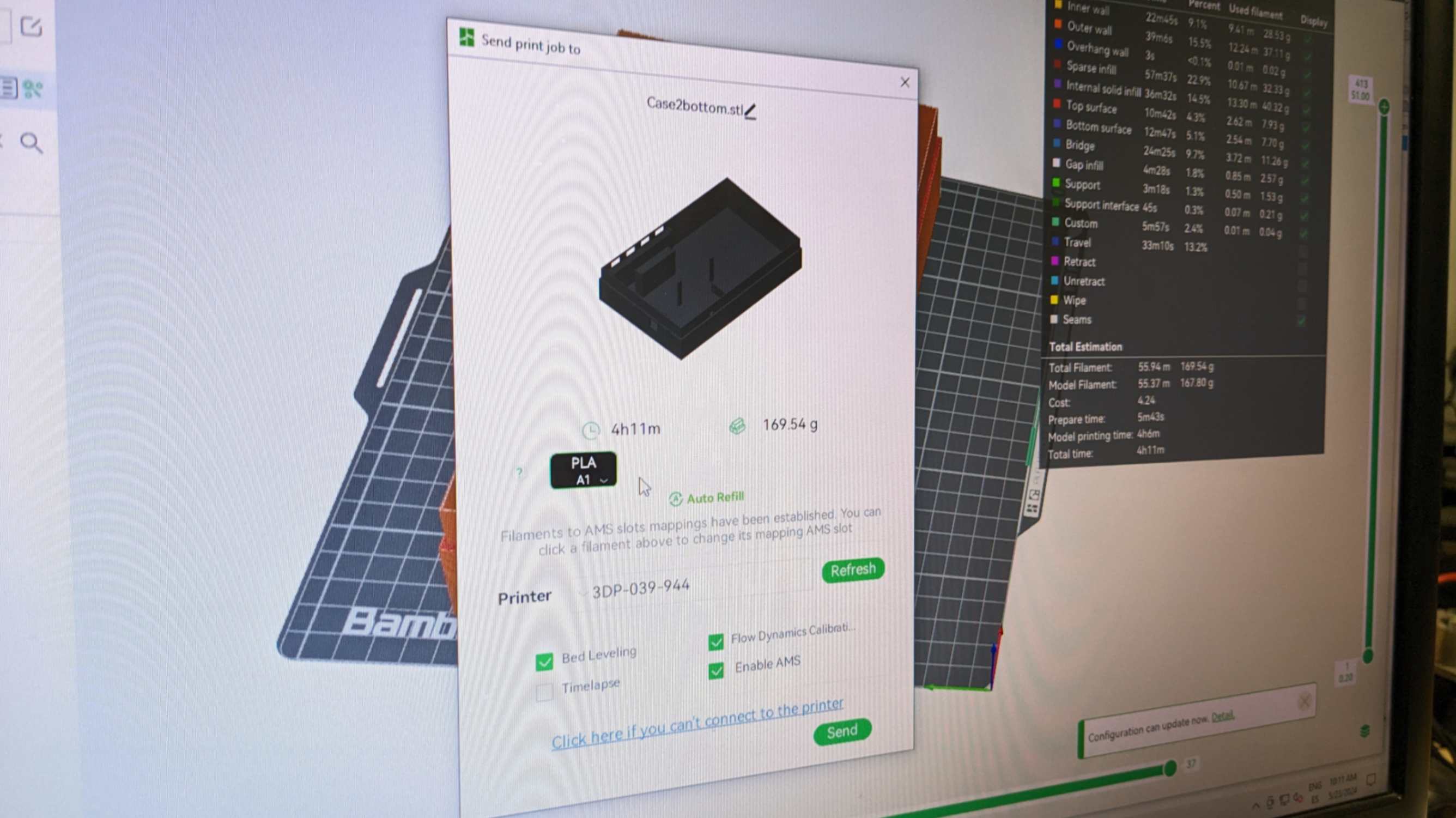
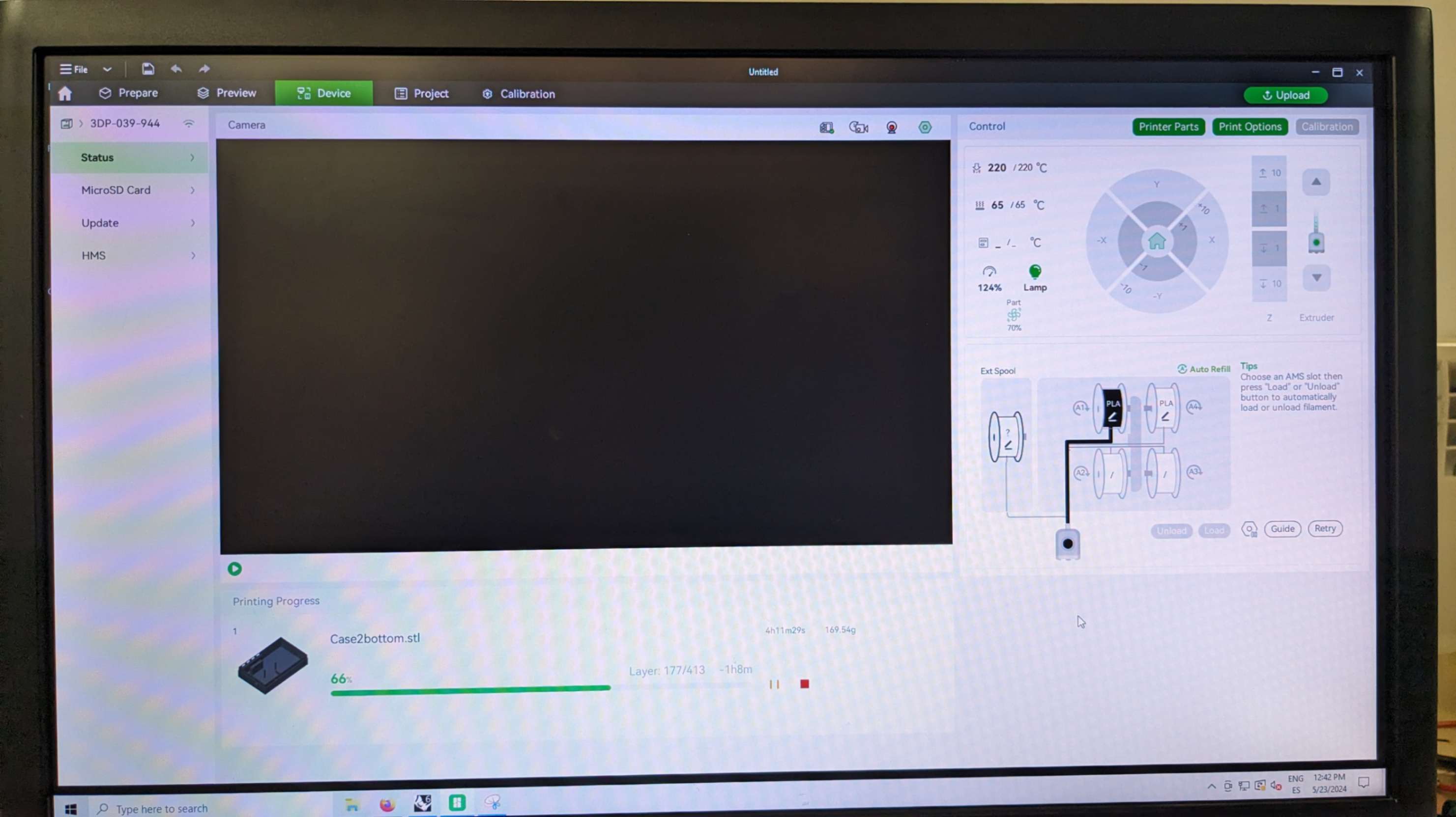
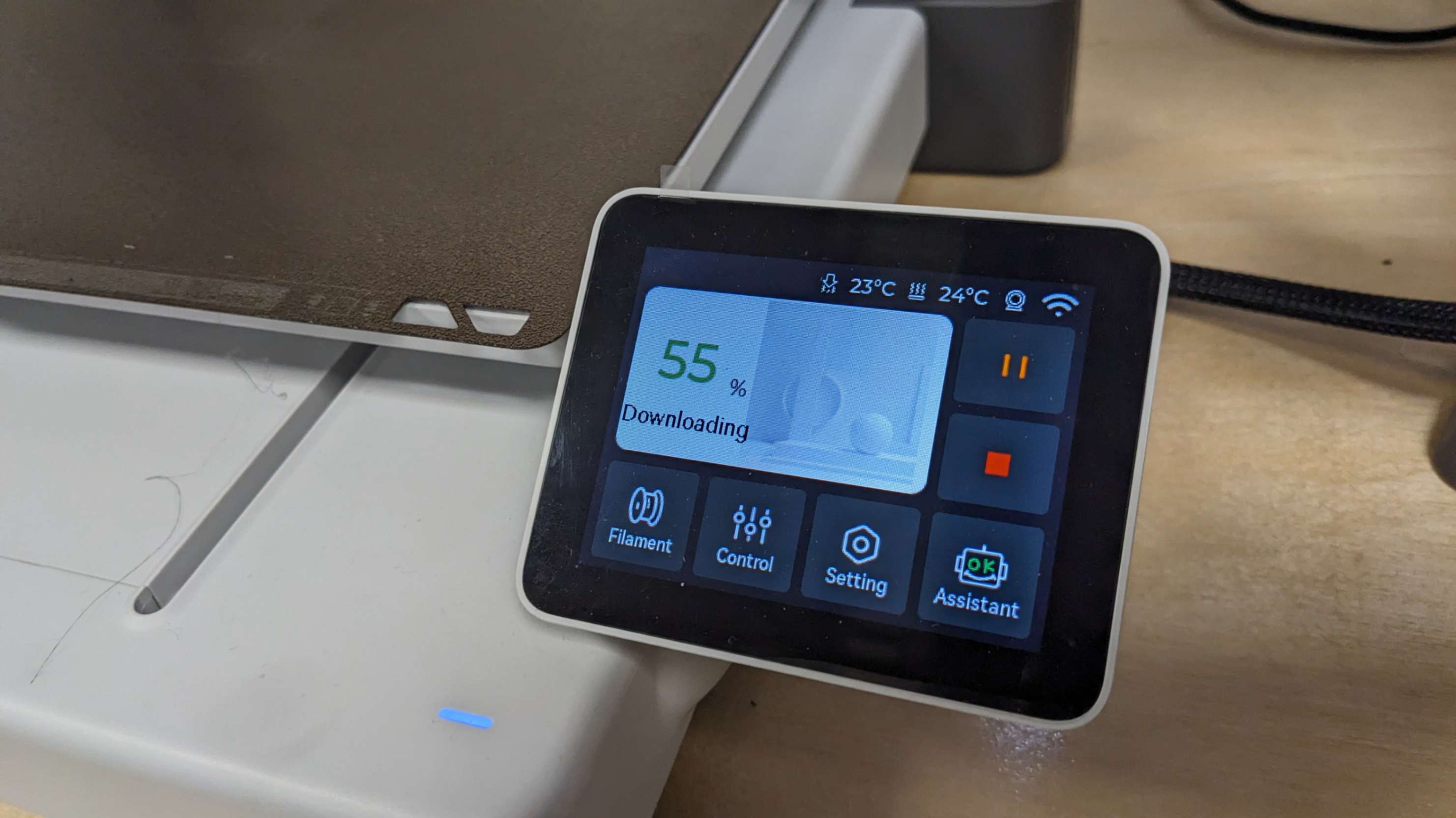
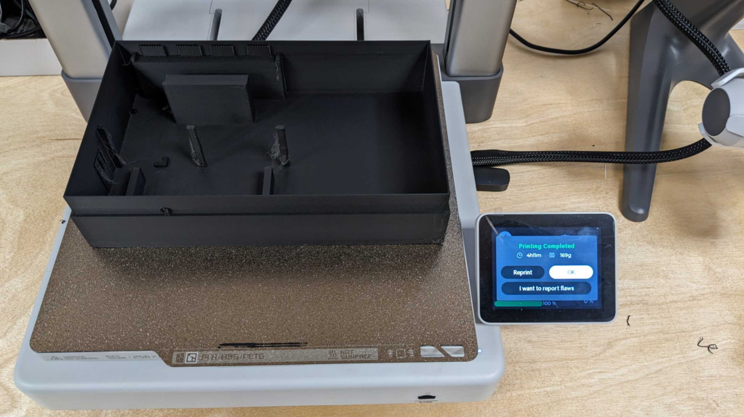
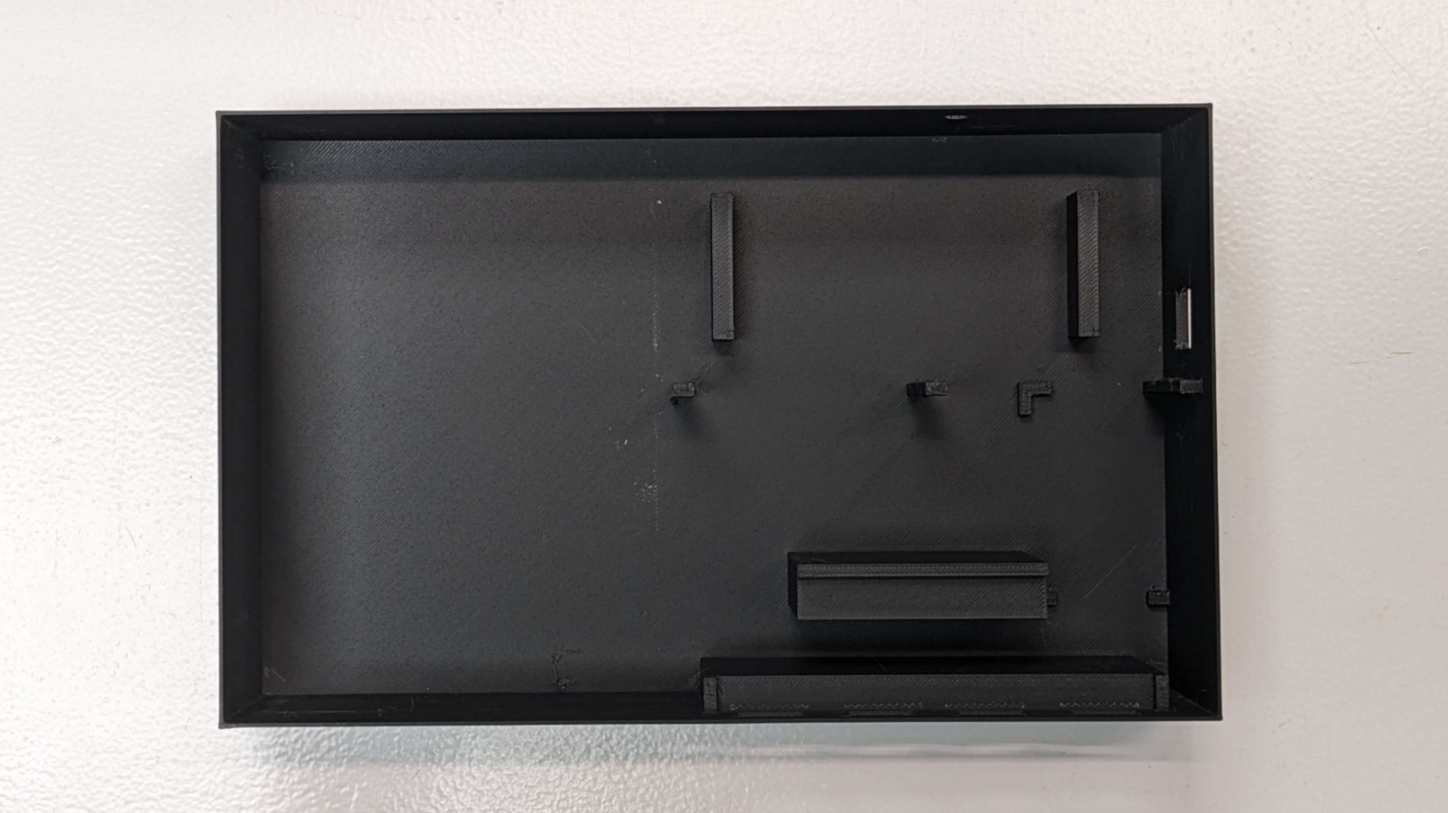
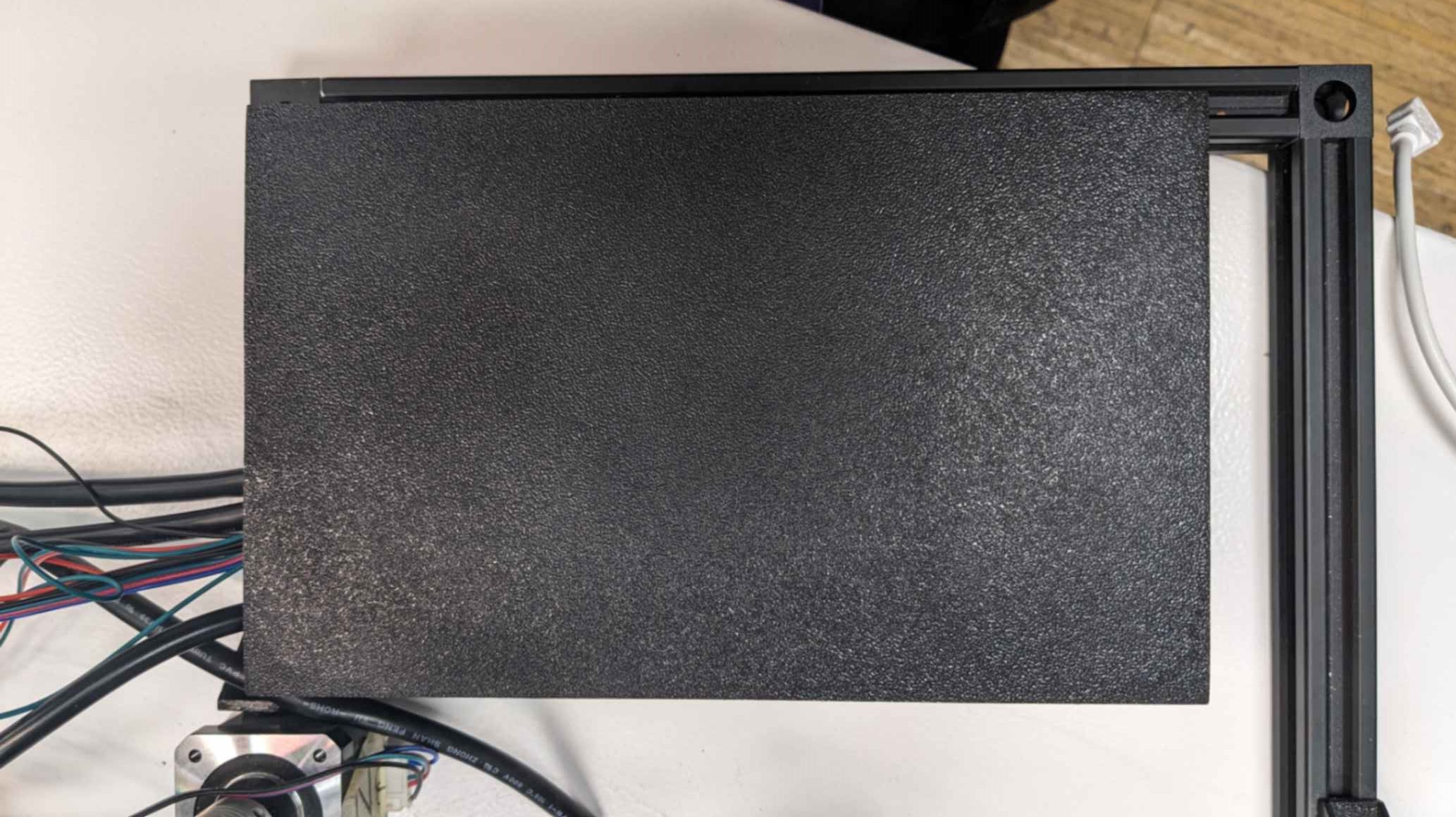
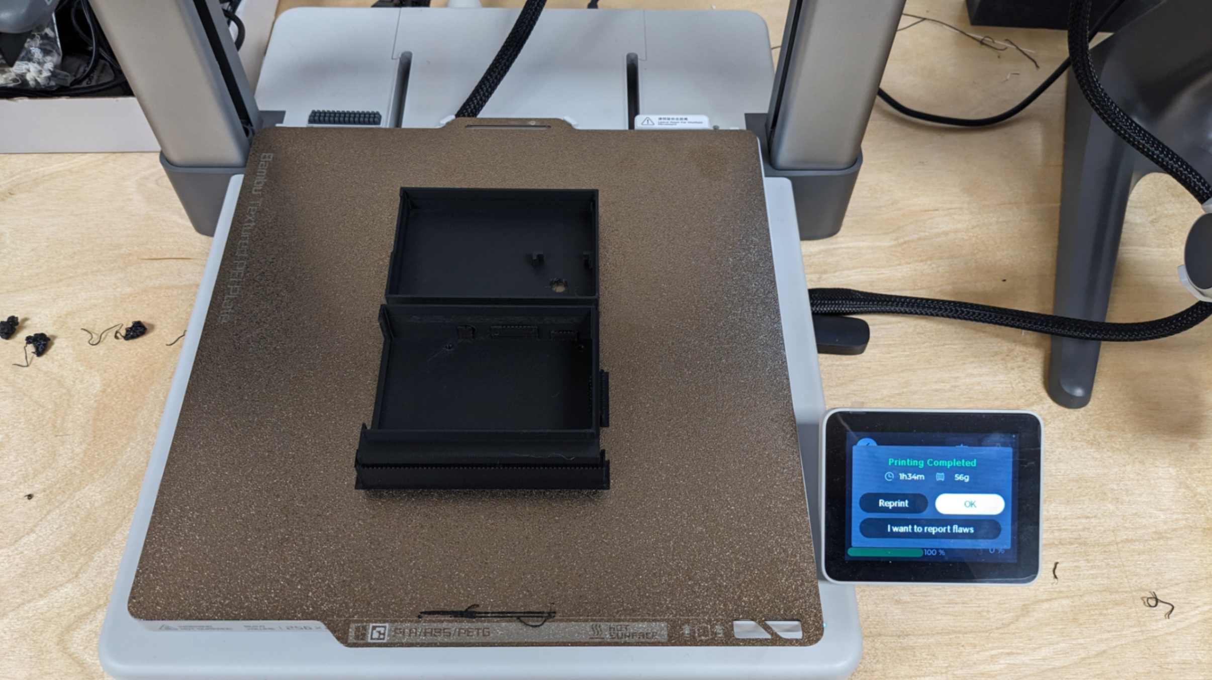
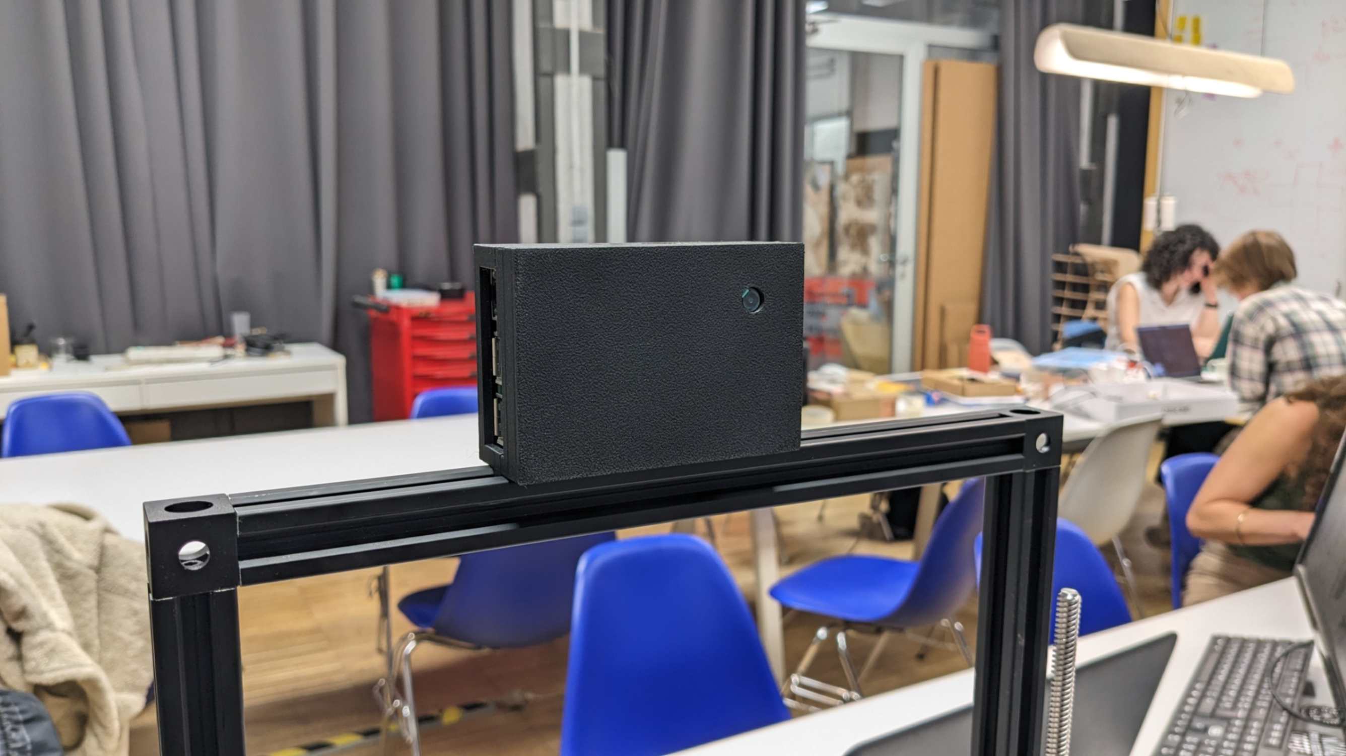
Then I made a 3D model in Rhino. The basic design rules were simple black bento boxes, minimal printing time, and stabilised components securely. I mainly used Bambu Lab A1
package(1).3dm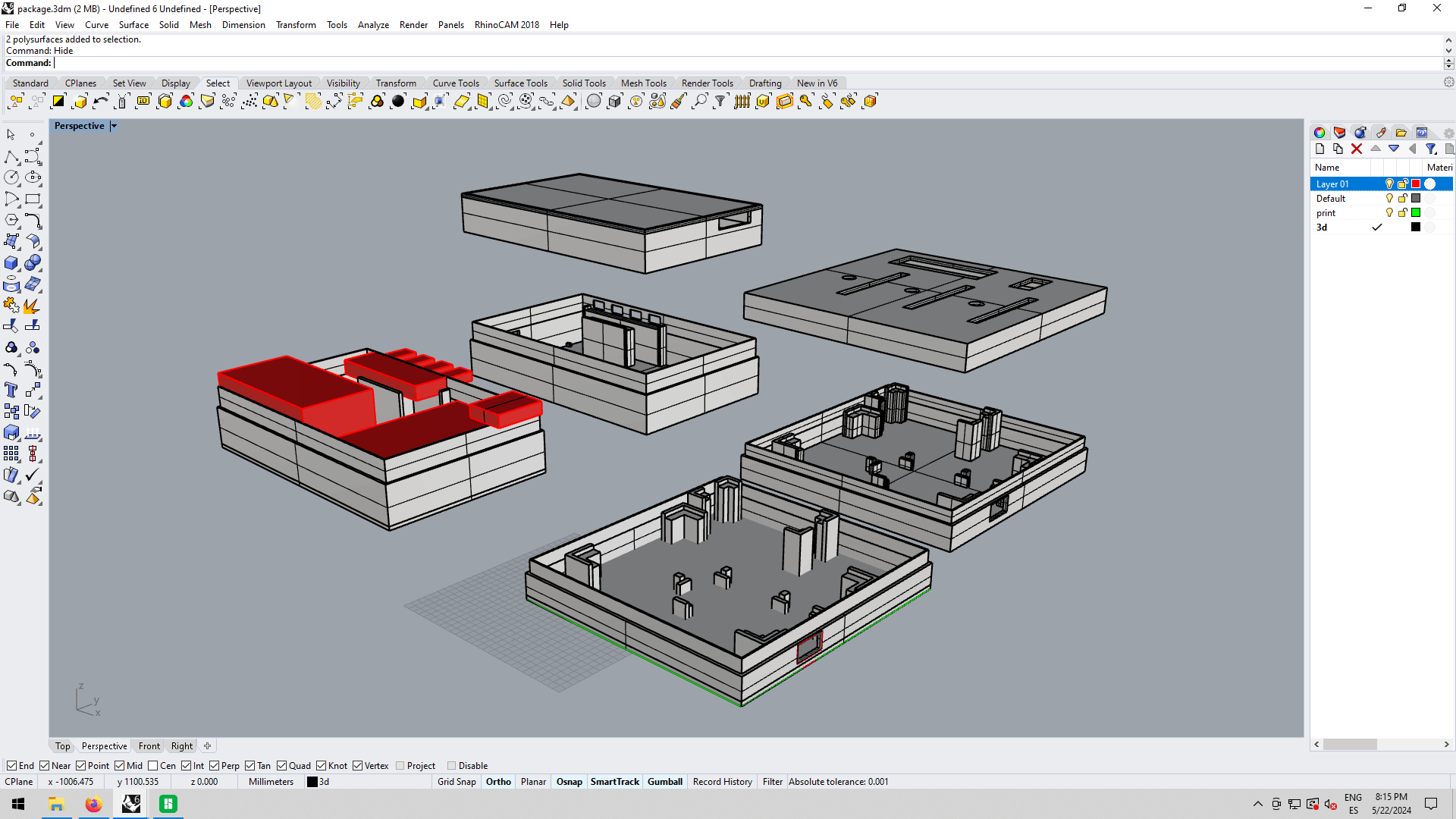
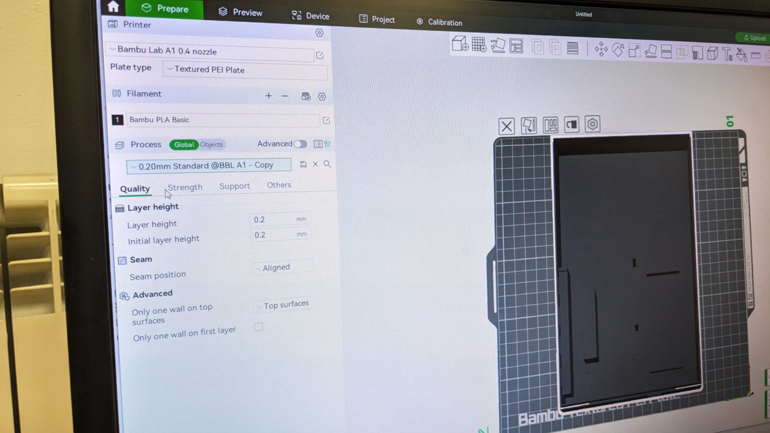
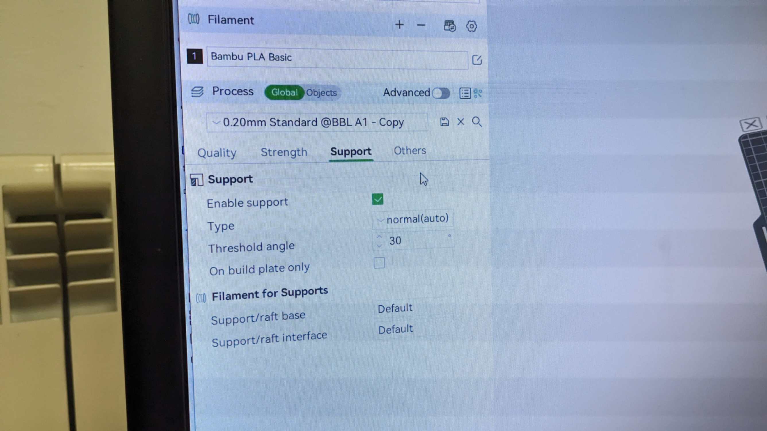
For the print setting, I used a default setting that was configured by the lab. The only thing I made sure of was to enable support and choose black PLA filament. Print job time was also most a half of Ender Pro, and the print finish was a lot nicer.
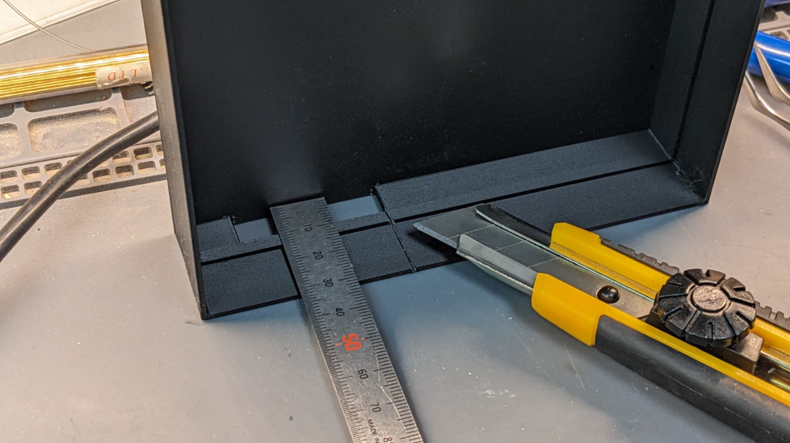
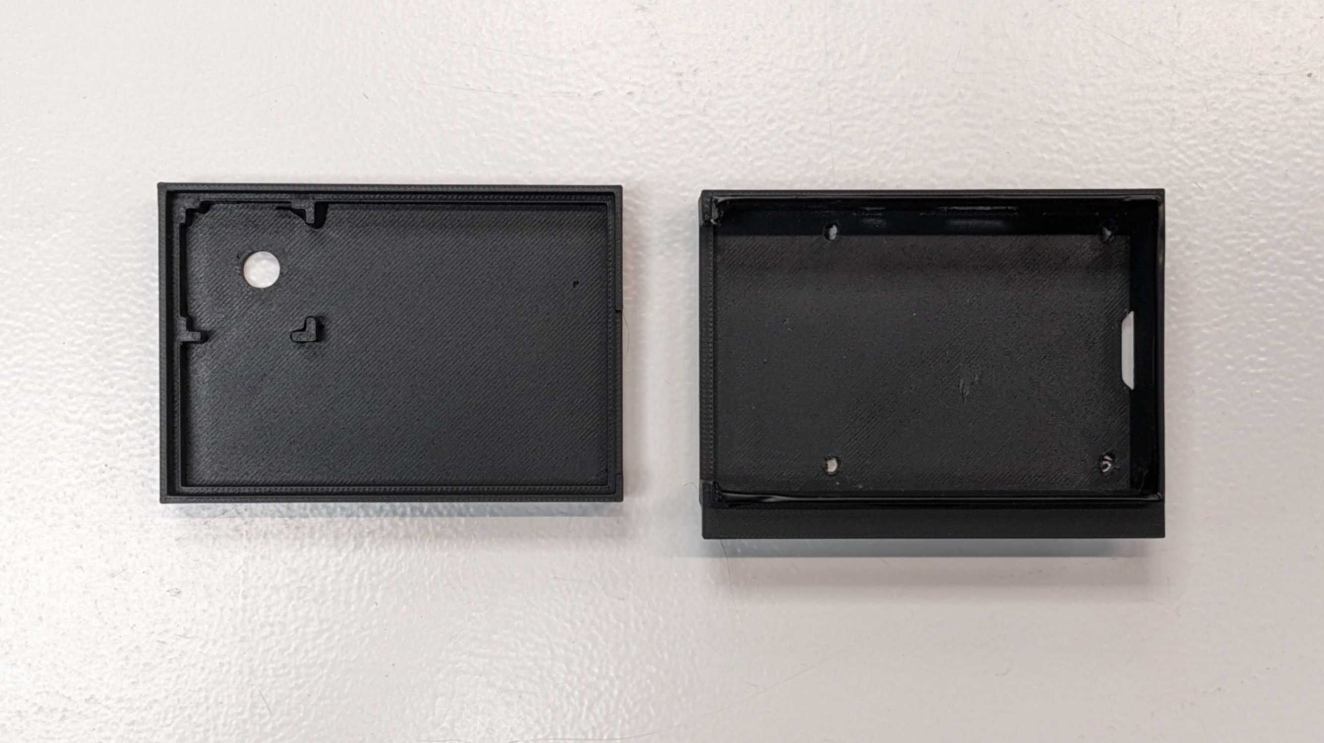
For some parts of the packaging, I needed to post-process due to design mistakes I made and tolerance issues.
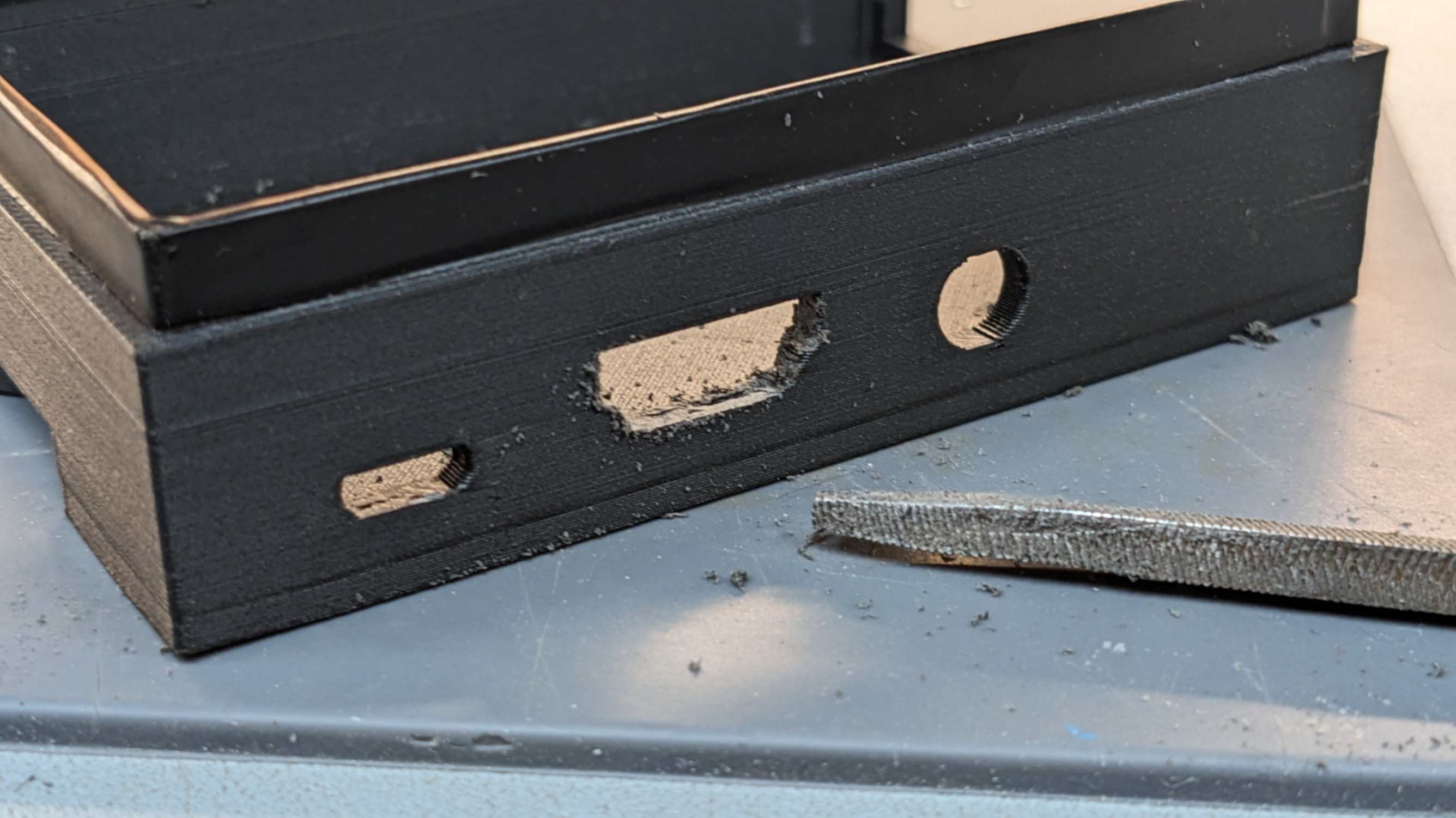
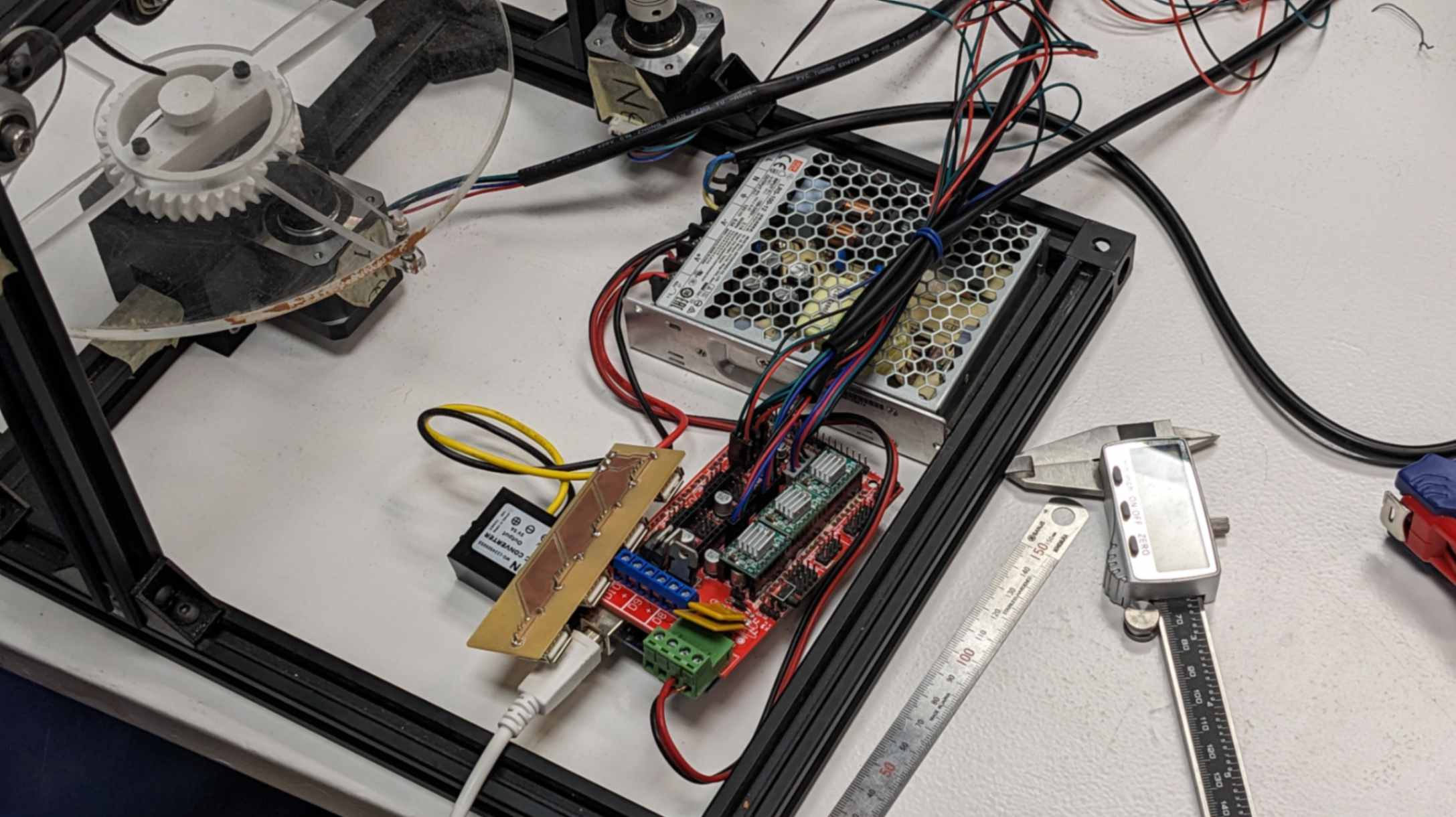
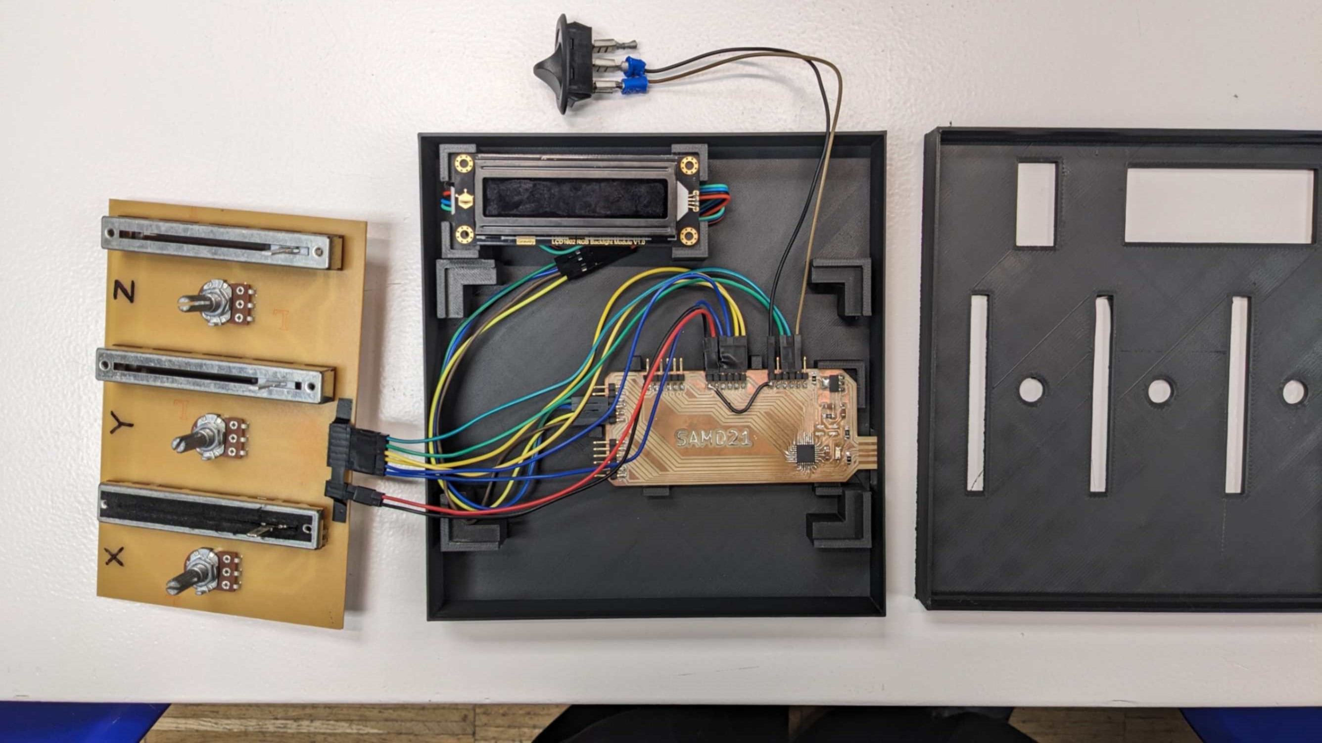
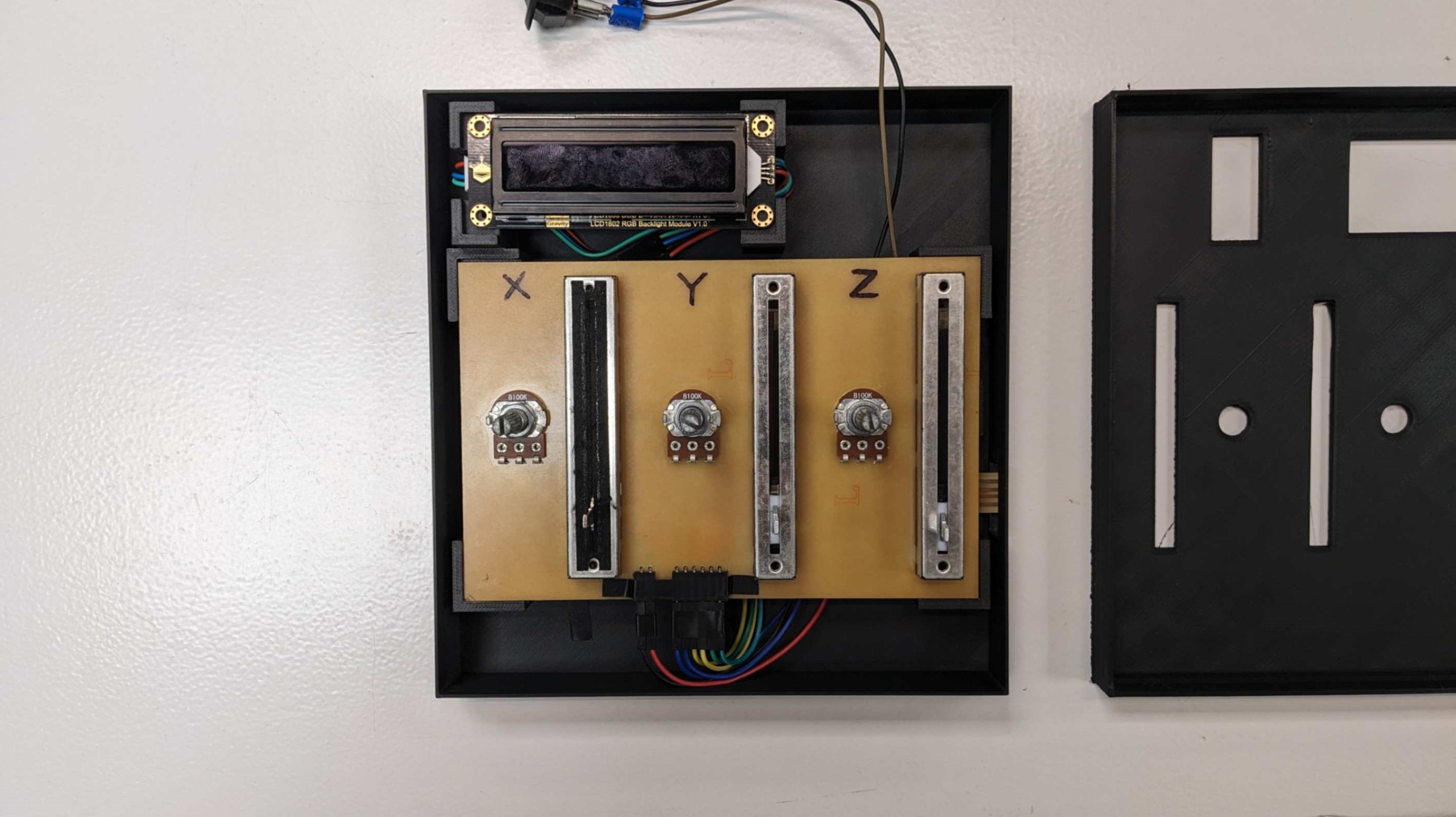
Wiring
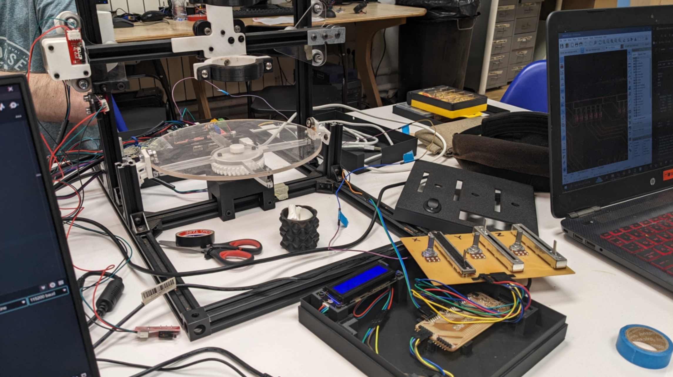
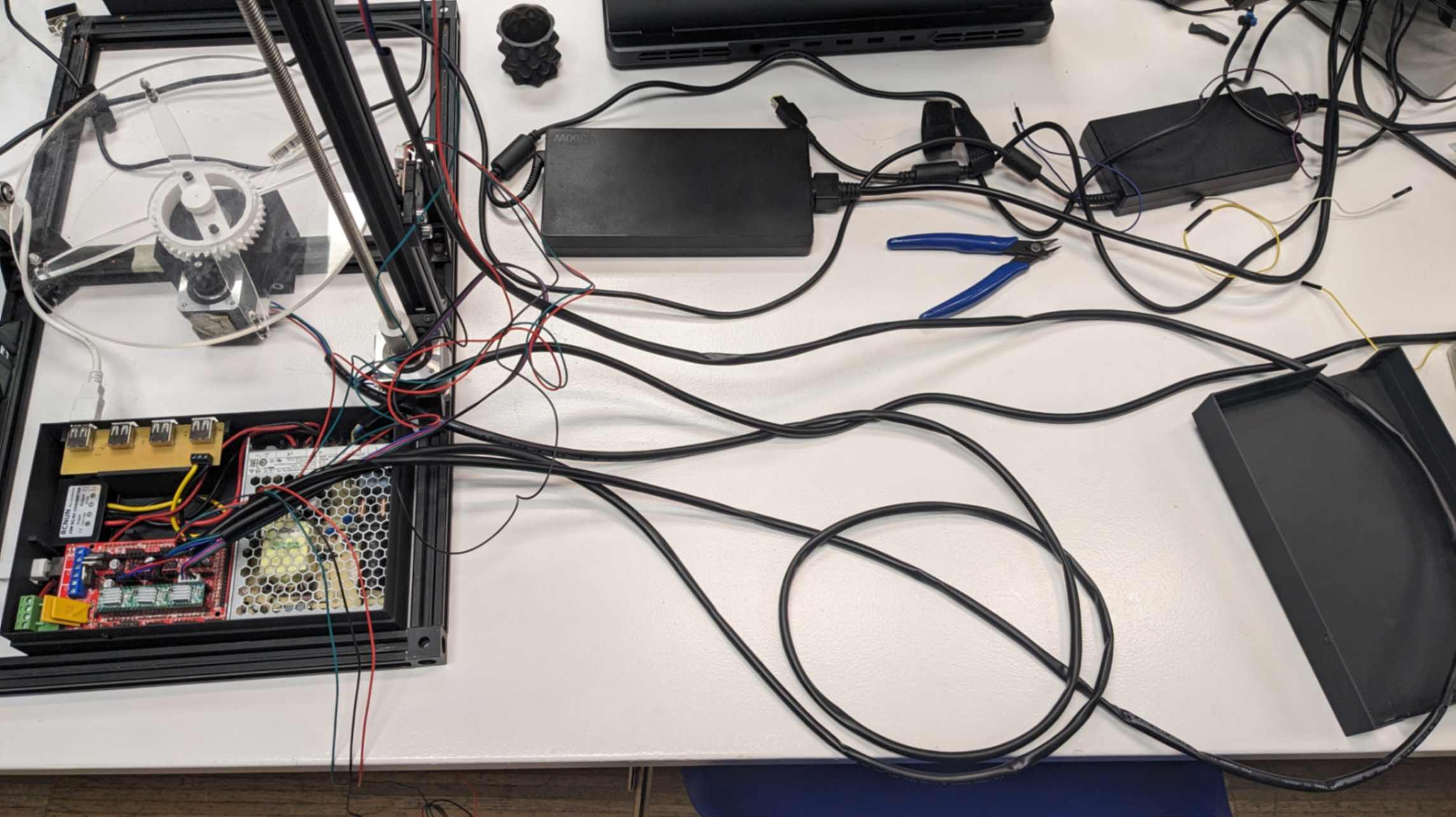
Even After the making of the package, my machine was very messy due to all the wires flying around the machine. So I decide to make those wires as tidy as possible. It was mainly making the wires shorter and covered with tubes.
To make the wires shorter, I was advised to use Heat-Shrinkable Tube Kit
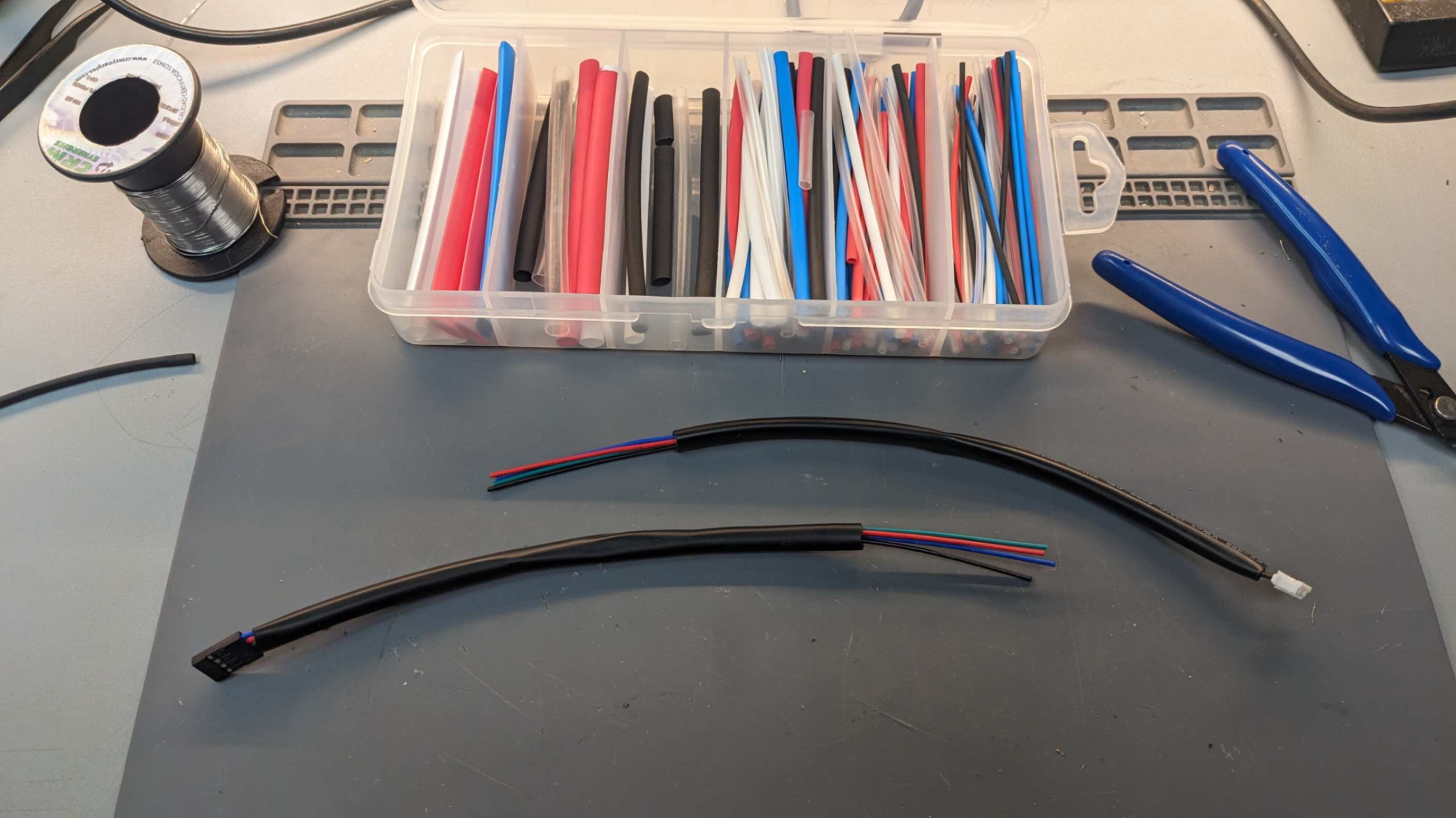
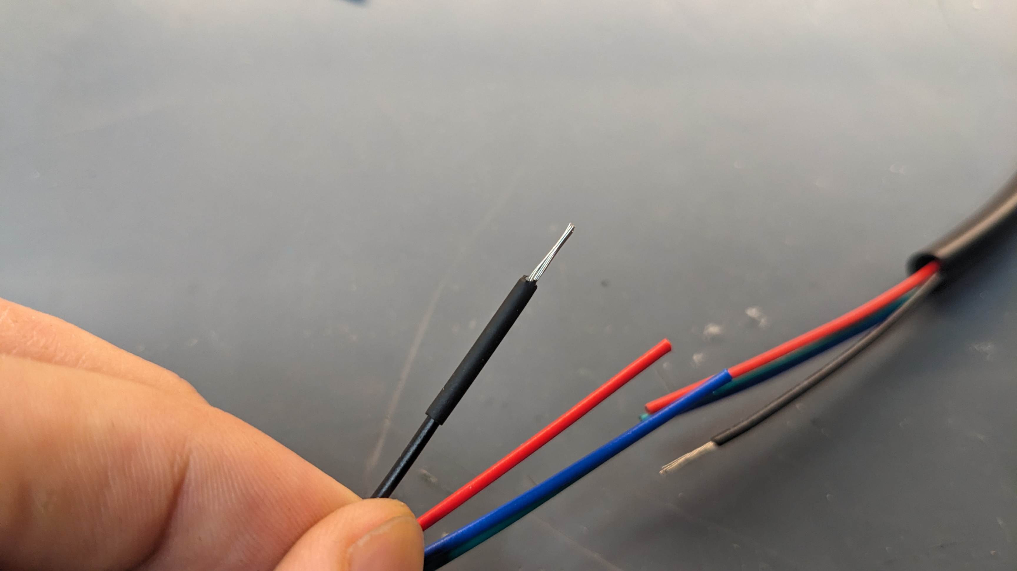
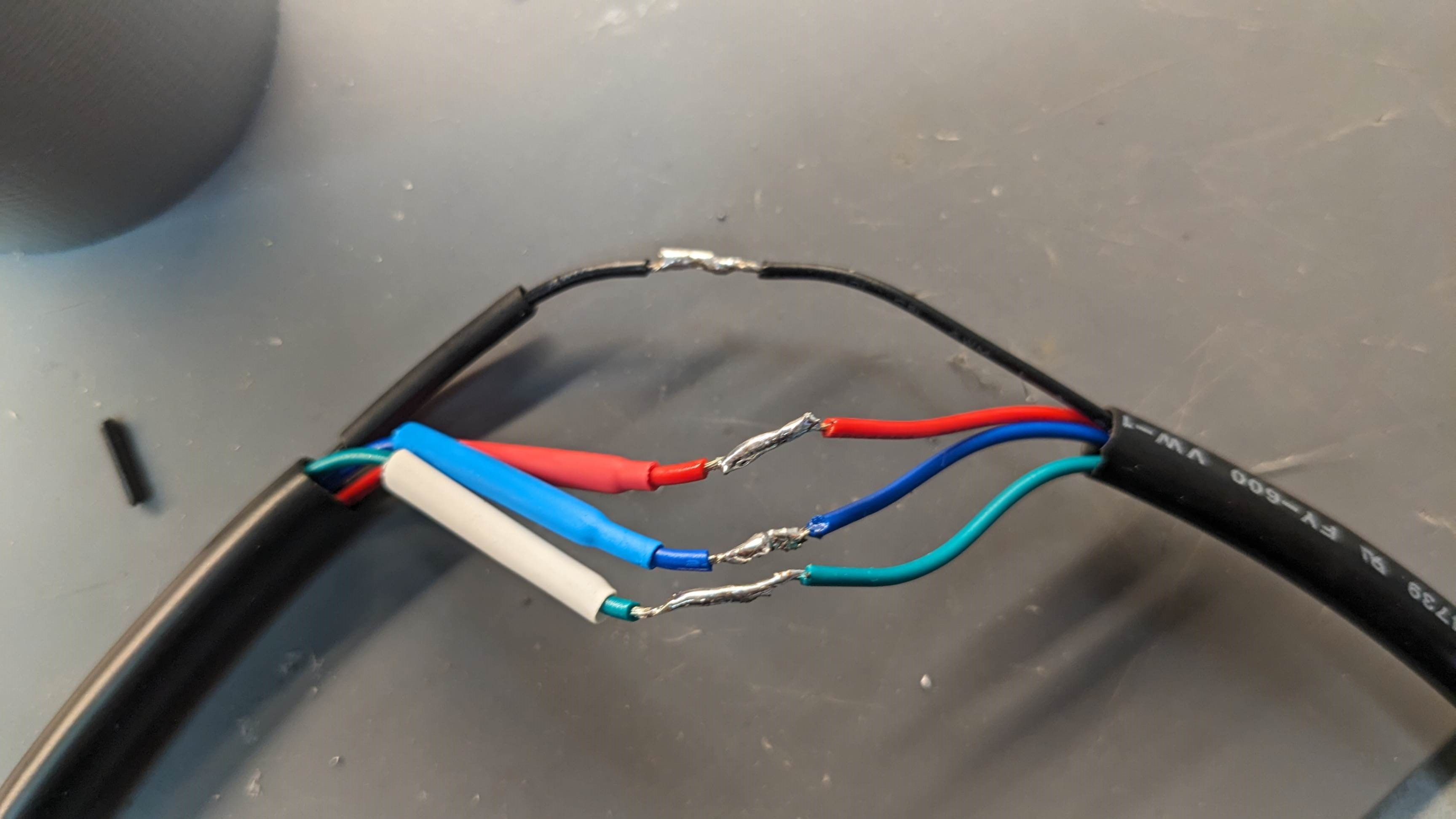
After cutting the wire, this tube needs to be placed on one side of the wire before reconnecting the wires. After twisting wires and soldering to reconnect, I slide this tube on top of the reconnection part and heat it by blowing a heat gun. This will cover the reconnecting part and make it more secure.
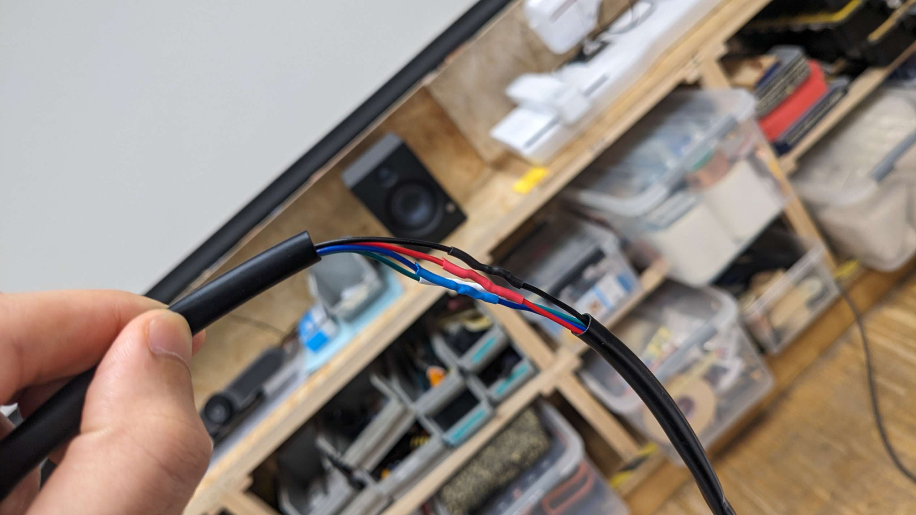
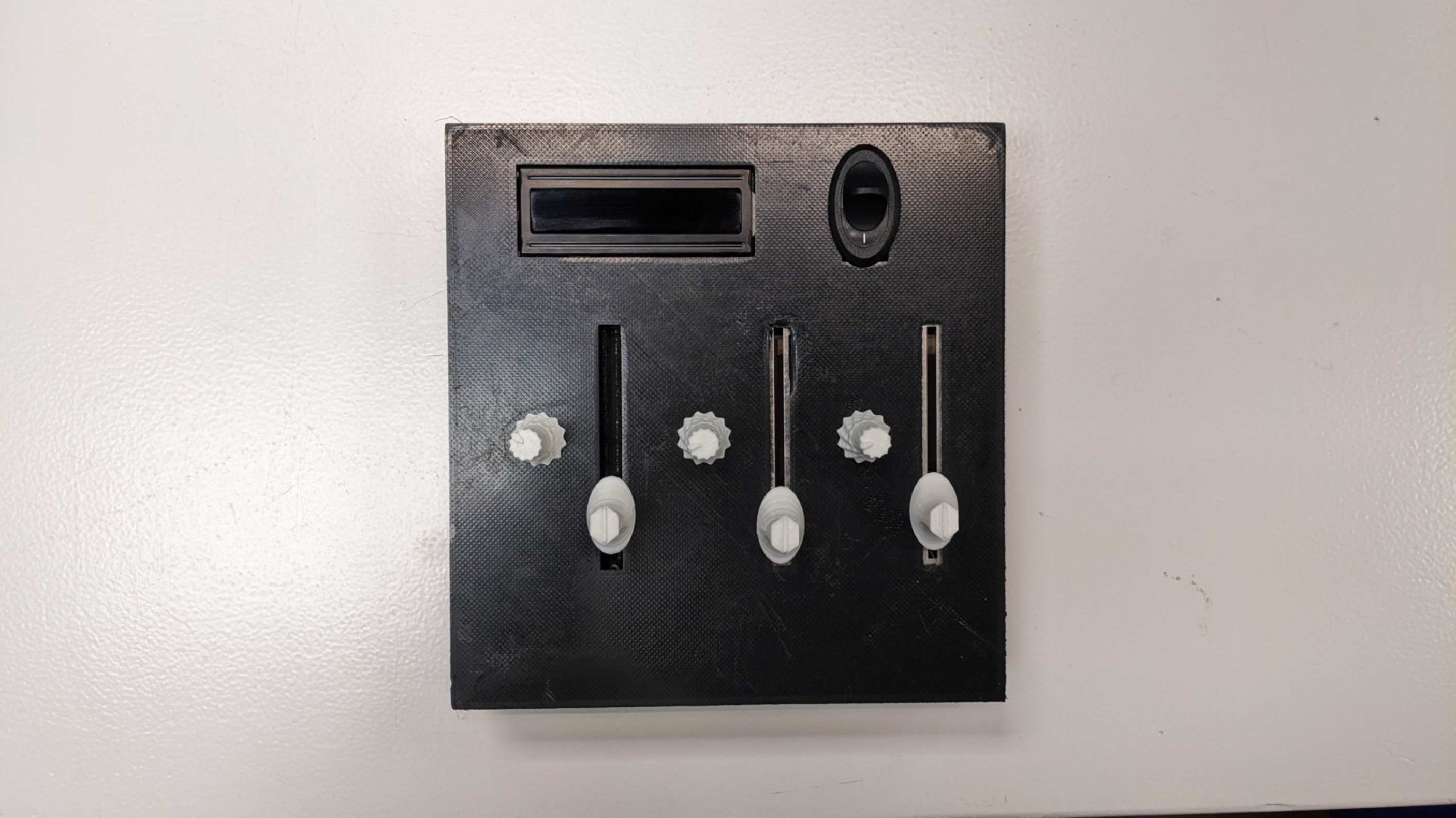
After I made the wires shorter, I simply slid the outer black tube and taped it with electrical tape.
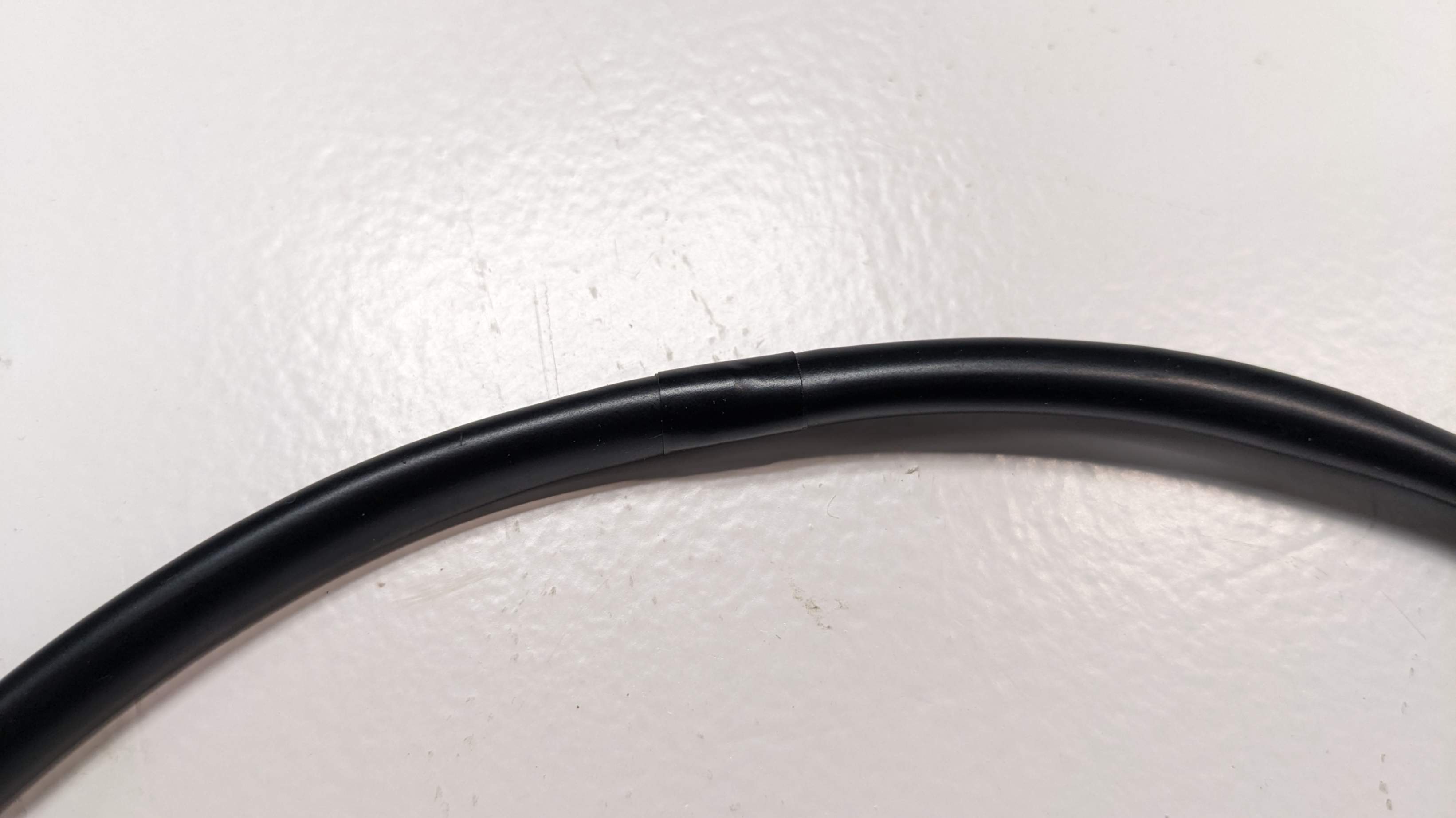
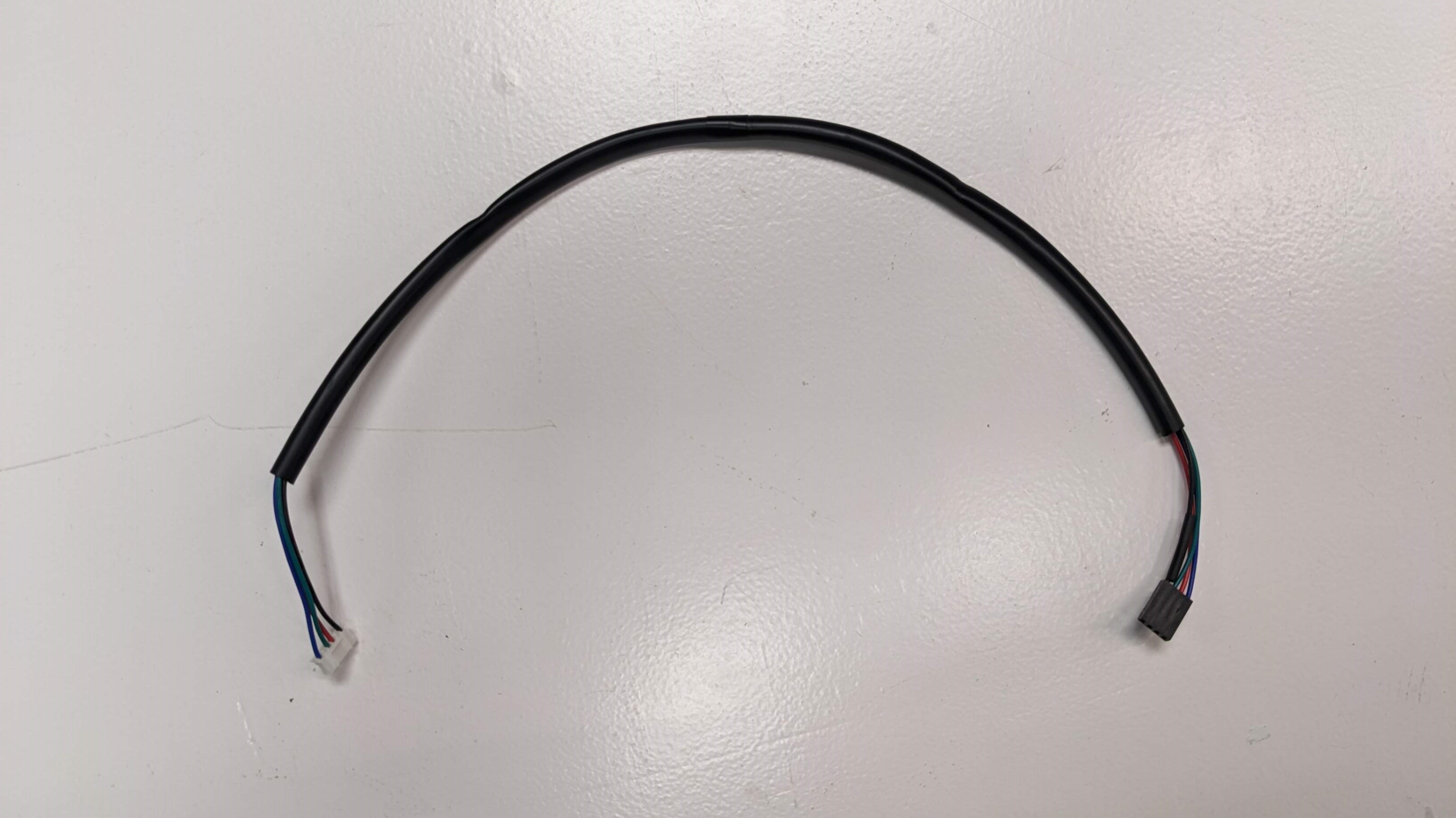
I repeated the same process for all the wires and as a result, my machine looked a lot cleaner.
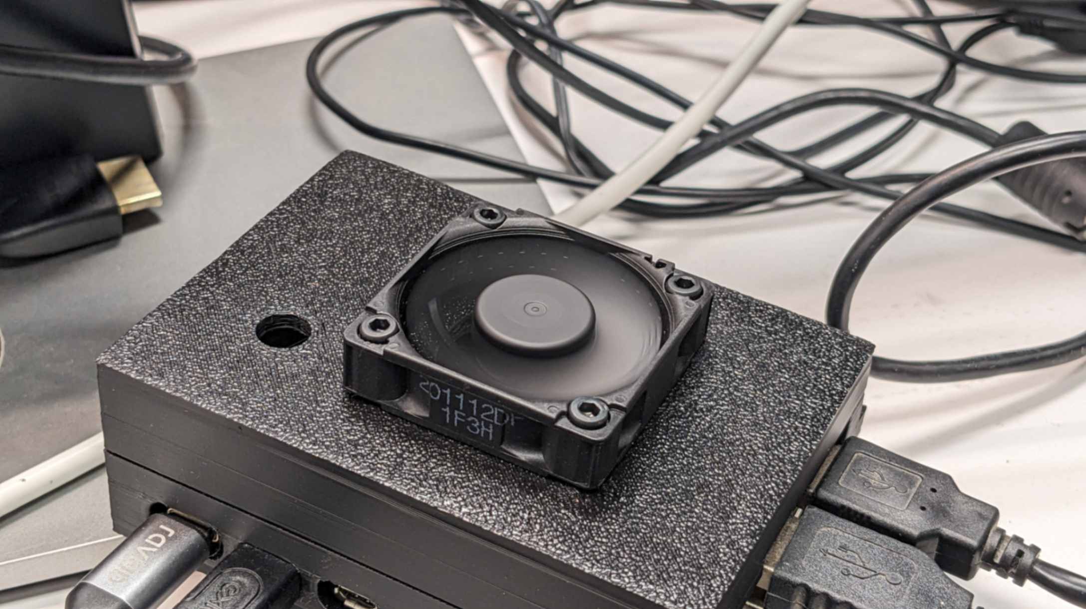
Fan for Raspberry Pi
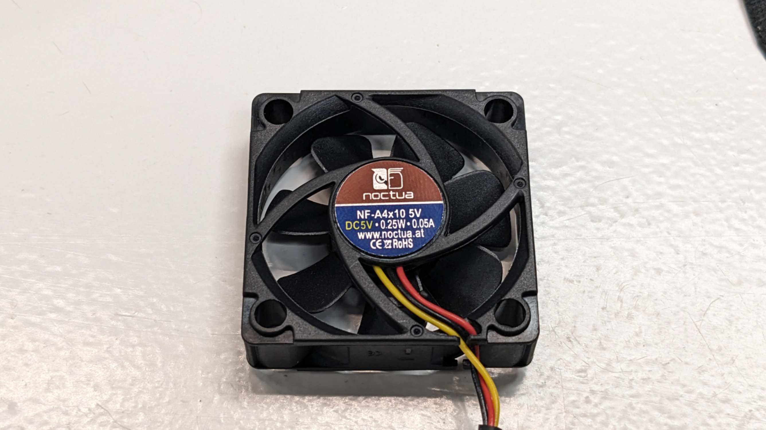
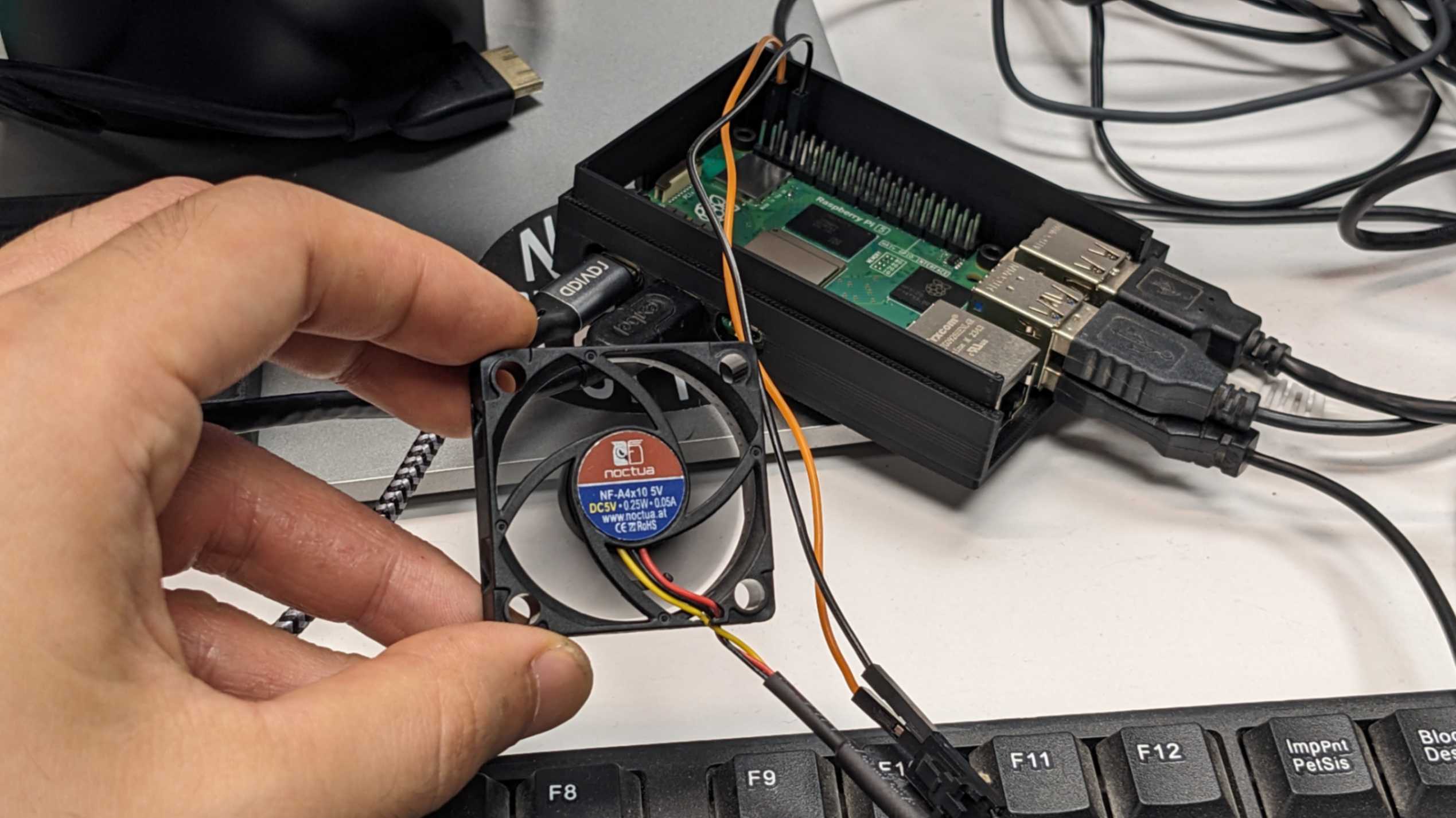
Since my Raspberry Pi got really hot I needed to include some kind of cooling system to it. The simplest way is to put an aluminium heat sink on top of the heated spots However I was not able to find enough heat sink. Instead, my tutor advised me to include a small fan which was available in the lab. It was Noctua NF-A4x10 5V
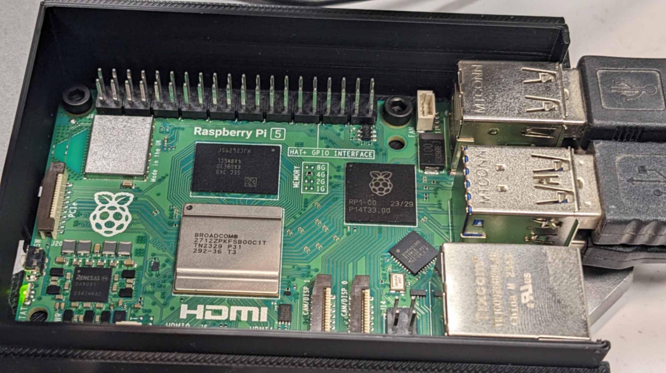
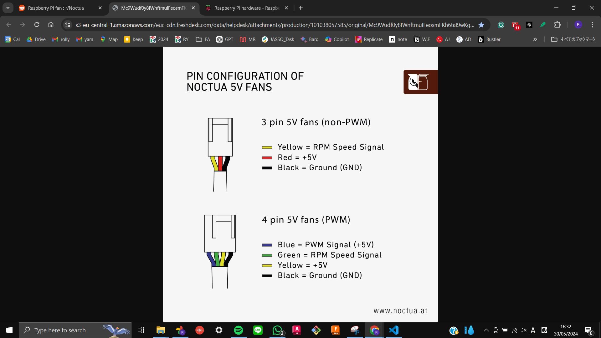
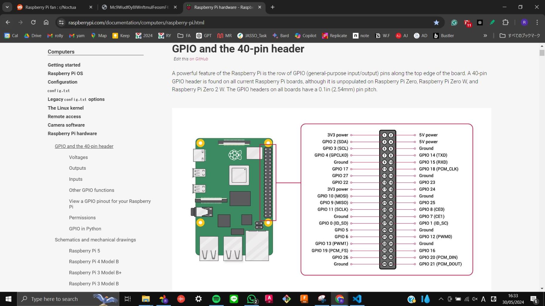
Since this module works with 5V, I just needed to connect 5V and GND by 2 wires. Raspberry Pi has many pins exposed and uses a 5V power pin and a GND pin for the fan.
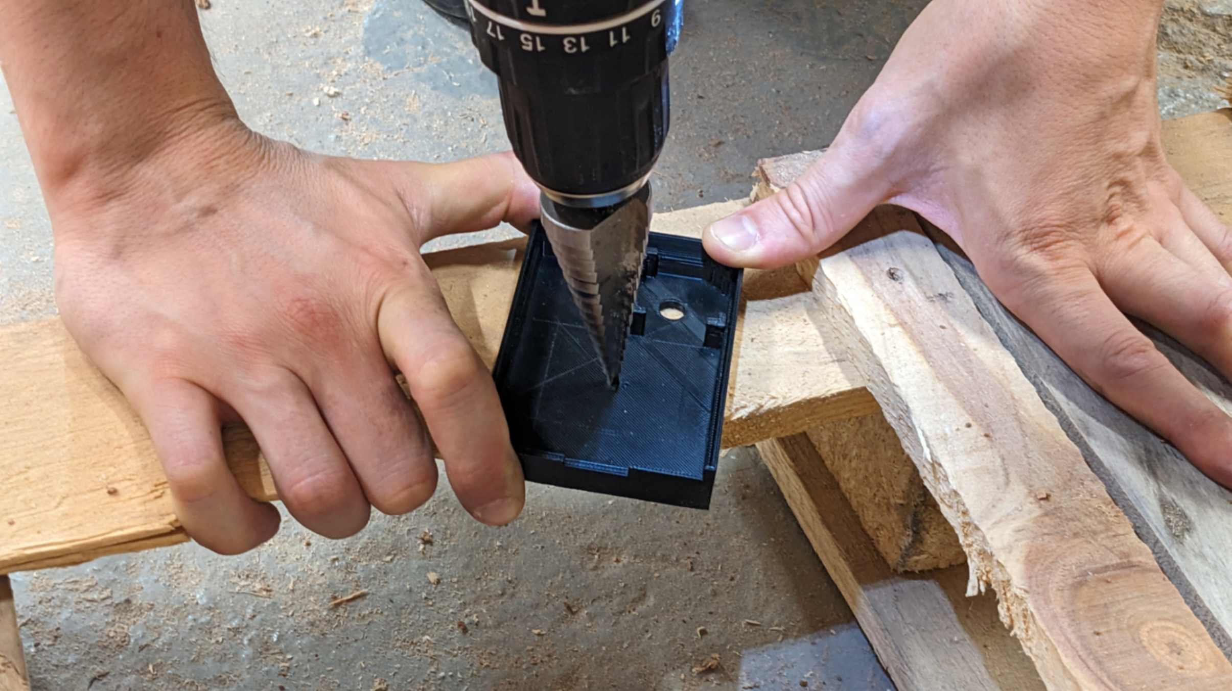
For the physical installation of the fan, I needed to make a hole for the air to blow in and out. I simply used a fan to drill my 3D-printed piece. Thank you to my tutor Adai for helping me with this.
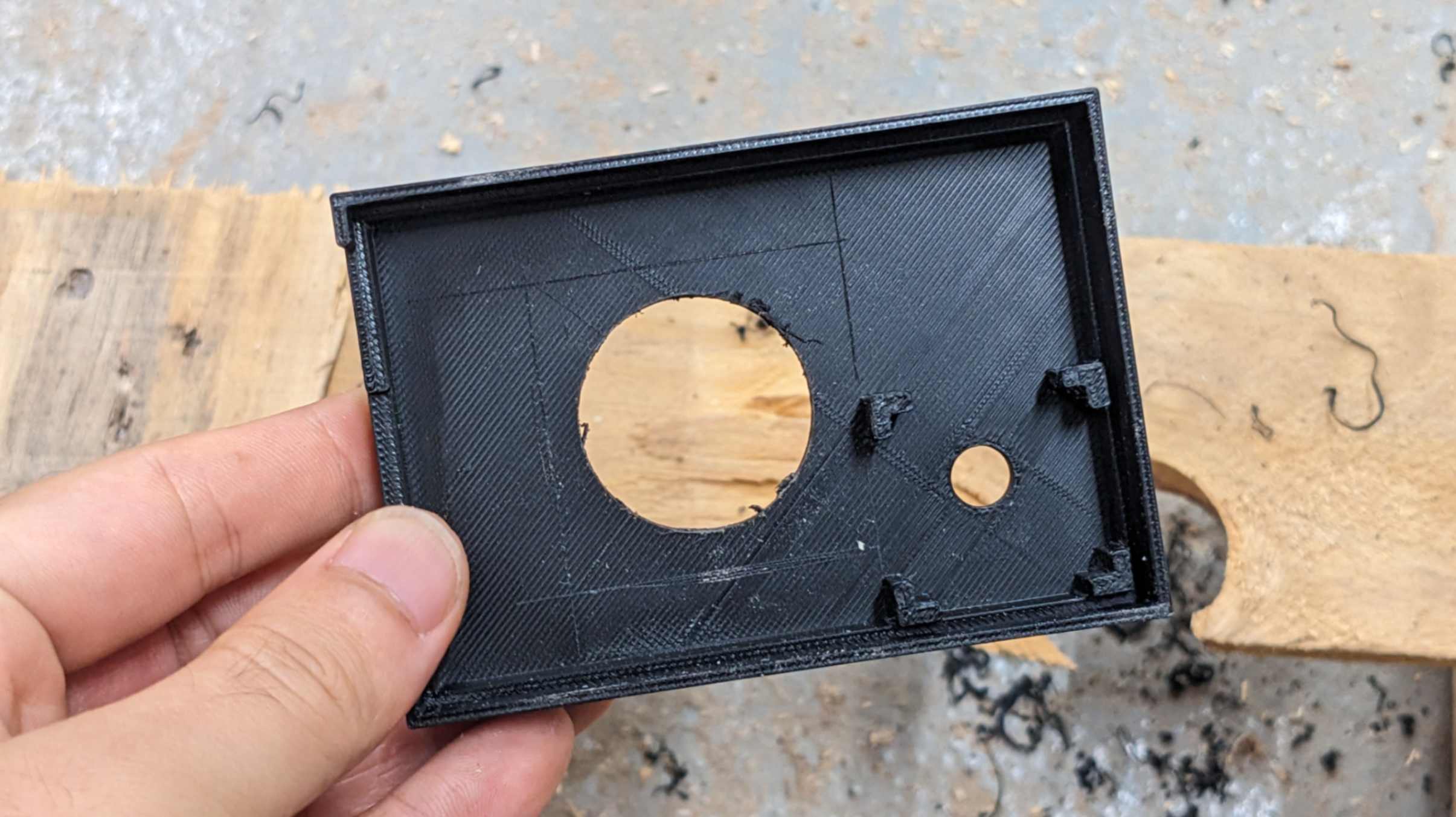
In the end, I was able to add a cooling fan to my Raspberry Pi packaging.